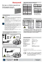
background image

Hybrid™ Manifold 

© Blichmann Engineering, LLC 2019

7

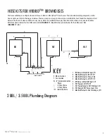
HOSE KITS FOR HYBRID™ BREWHOUSES

X

X

X

HLT

MT

BK

HE

Input Manifold

Output Manifold

E

E

E

X

X

X

X

X

X

X

X

X

X

X

X

X

X

E

E

E

E

1

2

3

4

5

6

7

8

9

T

L

KEY

E - Elbow Location

T - Tee Location

Ex - 6” Extension Location


- Pump


- 3 Way L Valve


- 3 Way T Valve


- Butterfly Valve

T

L

X

2 BBL / 3.5 BBL Plumbing Diagram

Ex

1 - BK Dump to Manifold Input, 4ft

2 - Manifold Output to BK CIP, 5ft

3 - Manifold Output to Pump, 28in 

4 - Manifold Output to MT CIP, 5ft

5 - MT Dump to Manifold Input, 4ft

6 - HLT Pump to MT CIP, 8ft

7 - HLT Pump Output to HLT Whirlpool, 5ft

8 - HLT Dump to HLT Pump Input, 18in

9 - Manifold Output to Heat Exchanger, 8ft

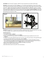
We have available pre-confi gured hose kits for our 2 BBL to 7 BBL Hybrid

 Brewhouses. The intended plumbing diagram as well as 

hose lengths are listed in the diagrams below. There are numerous ways to connect your manifold. We have found the diagrams listed  
below to be the most clean and effi  cient way to assemble the manifold. Please pay attention to the elbow, tee and valve locations. 
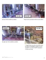
Reference photos below for the 2 BBL and 3.5 BBL (

FIGURES 11 - 16)

. Reference photos below for the 5 BBL and 7 BBL 

(

FIGURES 17 - 24)

.

Содержание Hybrid Manifold

Страница 1: ...them completely before use If you do not understand them or have any questions contact your retailer or Blichmann Engineering www BlichmannEngineering com before use Sections labeled Caution can lead to equipment damage or unsatisfactory performance of the equipment Please read these sections thoroughly If you have any questions contact your retailer or Blichmann Engineering www BlichmannEngineeri...

Страница 2: ...EMA 5 15P Power Cord 1 BE 001547 00 Barrell Plug 2 BE 001533 00 5 16 18 x 2 5 SS Screw 4 BE 001216 00 5 16 SS Washer 12 BE 001030 01 5 16 SS Nut 12 BE 001543 00 Power Cord 4 ft 1 BE 001573 00 5 16 x 1 5 OD Fender Washer 4 Item Number Description Quantity Base Manifold 1 BE 001401 00 1 HP Pump 1 BE 001433 00 1 HP VFD 1 BE 001425 01 Power Cord 1 BE 001481 00 VFD Cord 1 BE 000296 00 9 16mm Gland Conn...

Страница 3: ...umpfromthebase Placeawasheroneachboltandinsertthe assembledboltsthroughthebottomofyourselectedholeconfiguration SeeFigure2 Place anotherwasherandnutontoeachboltandthreadallofthewaydowntothebase Thisshould holdtheboltinplace NOTE Wedonotrecommendtighteningallofthewayasyoustillneedto adjusttheboltforwardsorbackwardsintheslot PleaseseeFigure4toseethecorrectconfigura tionofhowtoassemblethewashers bolt...

Страница 4: ...yourpumpiscontrolledbyaVariableFrequencyDrive thenyouwillnotneedtheswitch andyou canskipaheadtoSTEP6 YoucanremovetheswitchandmountyourVFDinitsplaceshouldyoudesire ManifoldSwitchWiring 1 LoosenGlandConnectorB SeeFigure7 2 Loosenall4screwsholdingthecoverontheswitch SeeFigure7 3 RemoveswitchcoverfromhousingandslidethewirethroughGlandConnectorBtogiveyourselfroomtomovetheswitch SeeFigure8 4 Runthewiref...

Страница 5: ...Hybrid Manifold Blichmann Engineering LLC 2019 5 SlideWire Through SlideWire Through Gland Connectors Figure7 Figure8 6 4 2 Figure9 A B ...

Страница 6: ...tarydiaphragmvalveincludedtohelpcontrolflow IfyourpumputilizesaVFD thenthediaphragmvalve useisoptional Atthispoint themanifoldinstallationiscomplete Youcanattachvalvesandhosestosuityourowncustom configuration Thebottomrowofportsaretheinletstothepumpandthetoprowofportsaretheoutlets NOTE Contactusor checkourwebsitewww blichmannpro comformoreinformationonpre configuredhosekitsorcustomhosepackagestofi...

Страница 7: ...o BK CIP 5ft 3 Manifold Output to Pump 28in 4 Manifold Output to MT CIP 5ft 5 MT Dump to Manifold Input 4ft 6 HLT Pump to MT CIP 8ft 7 HLT Pump Output to HLT Whirlpool 5ft 8 HLT Dump to HLT Pump Input 18in 9 Manifold Output to Heat Exchanger 8ft Wehaveavailablepre configuredhosekitsforour2BBLto7BBLHybrid Brewhouses Theintendedplumbingdiagramaswellas hoselengthsarelistedinthediagramsbelow Therearen...

Страница 8: ...oallow easeofportability thisreducestrippinghazards Pleasenotetheorientationofthesanitarydiaphragm valve Topviewofmanifold Frontviewofmanifold T shapedthree wayvalveontopofthemashtun allowstheflexibilitytobypassthemashtunkettle oritcanbeturnedforspargingorCIP Clean In Place FIGURE11 FIGURE12 FIGURE13 FIGURE14 FIGURE15 FIGURE16 ...

Страница 9: ...Valve Pump 3 Way L Valve 3 Way T Valve T 3 Way L Valve 3 Way L Valve L X 5 BBL 7 BBL Plumbing Diagram Ex X 10 1 BK Dump to Manifold Input 5ft 2 Manifold Output to BK CIP 6ft 3 Manifold Output to Pump 3ft 4 Manifold Output to MT CIP 8ft 5 MT Dump to Manifold Input 4ft 6 HLT Pump to MT CIP 8ft 7 HLT Pump Output to HLT Whirlpool 9ft 8 HLT Dump to HLT Pump Input 3ft 9 Manifold Output to Heat Exchanger...

Страница 10: ...manifoldassembled FIGURE17 Pleasenotetheorientationoftheteesandelbows FIGURE18 Straightviewofthemanifoldassembled FIGURE19 T shapedthree wayvalveontopofthemash tunallowstheflexibilitytobypassthemash tunkettleoritcanbeturnedforspargingor CIP Clean In Place FIGURE20 ...

Страница 11: ...tthehosesaretuckedundertoallow easeofportability thisreducestrippinghazards Pleasenotetheorientationofthetees andelbows Topviewofmanifold MashTunTemperature Sensorcanbemountedtotheoutputofthe manifoldfortemperturereadingsduringmash tunrecirculation FIGURE21 FIGURE22 FIGURE23 FIGURE24 ...

Страница 12: ... in any country where the product is distributed ________________________________________ B Limitations of Warranty 1 Any implied warranty that is found to arise by way of state or federal law including any implied warranty of merchantability or any implied warranty of fitness is limited in duration to the terms of this limited warranty and is limited in scope of coverage to this warranty Blichman...

Отзывы: