


Hybrid™ Manifold
© Blichmann Engineering, LLC 2019
4
STEP THREE:
Attach the tri-clamp (TC) sight glass and NPT to Tri-Clamp (TC) adapter (if necessary) to the inlet of the pump.
STEP FOUR:
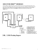
Attach the butterfly valve to Port B in
Figure 6
. There are two different hole configurations on the base of the manifold.
Slide the pump forward or backward to determine your configuration. Once you’ve determined the configuration, clamp the TC butterfly
valve to the TC sight glass. Attach the top of the manifold to the base of the manifold with the supplied (4)
¼
” washers, (4)
¼
” x 2” bolts
and (4)
¼
” nuts utilizing the hole configuration that best lines up with the pump location. You may need to slide the pump and the top
of the manifold forwards and backwards to line up with the holes in the base of the manifold. See
Figure 5 and Figure 6.
Once you have
mounted the top of the manifold, you can now torque down all of the nuts and bolts.
NOTE:
Make sure to check the height of the pump
before tightening the mounting nuts and bolts.
STEP FIVE:
Wire the On/Off switch. (If your pump is controlled by a Variable Frequency Drive, then you will not need the switch, and you
can skip ahead to
STEP 6
. You can remove the switch and mount your VFD in its place should you desire.)
Manifold Switch Wiring
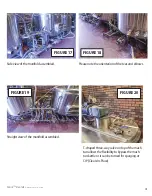
1. Loosen Gland Connector B. See
Figure 7
.
2. Loosen all 4 screws holding the cover on the switch. See
Figure 7
.
3. Remove switch cover from housing and slide the wire through Gland Connector B to give yourself room to move the switch.
See
Figure 8.
4. Run the wire from your pump through Gland Connector A on the switch housing. (You may first need to cut the plug off of the end of
your pump wire, and strip it so that it can be wired into the switch.) See
Figure 8
.
5. Place the stripped end of each wire into the corresponding terminal on the switch cover. The Hot wire should be connected to
terminal 2, the Neutral wire should be wired into terminal 4, and the Ground wire should be connected into terminal 6. (Ensure no
wires are loose and sticking out of the terminals.) See
Figure 9
. Tighten screws on the side to secure wires.
6. Slide wires back through both Gland connector A & B to place the switch back onto the housing.
7. Tighten all 4 screws to secure the cover to the switch.
8. Tighten both Gland Connector A & B around the wires to seal the housing.
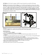
Figure 5
TOP
BASE
PORT B
Figure 6


