www.blaubergventilatoren.de
9
KOMFORT EC DE
The
KOMFORT EC DE400-1.5 ... DE1100-3.3
units are rated for
connection to single-phase alternating current power mains 230 V / 50-60
Hz via a pre-wired power cable with a euro plug.
The control unit compartment includes a terminal block with connected
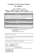
wires from the sensor control panel. The wiring diagram is shown in fig. 9 and
the functional diagram is shown in fig. 10.
The
KOMFORT EC DE2000-12 ... EC DE4000-21
units are rated for
connection to three-phase alternating current power mains 400 V / 50-60
Hz via insulated, durable and heat-resistant conductors (cables, wires) with a
matching cross section, in any case not below 4 mm2.
The referred conductor cross section is for reference only. While
selecting the conductors with respective cross section consider the
wire type, the maximum permissible conductor heating temperature,
its insulation, length and layout. Use copper wires only! The wiring
diagram is shown in fig. 11 and the functional diagram is shown in fig. 12.
The unit must be grounded in compliance with the valid electrical standards
of the user country!
Connect all the control and power conductors in compliance with the
terminal marking and polarity.
The rating plate with a terminal designation is placed inside of the
terminal box.
The terminal clamp marking corresponds to the marking on the wiring
diagram.
Route the conductors to the terminal box through the electric lead-in on
the unit panel to preserve the electrical protection class.
Cut power supply to the unit off by turning the automatic electric switch
QF to OFF position prior to any operations.
Take steps to prevent activation of the automatic switch before finishing
all the operations.
QF
CONNECTION TO POWER MAINS
WARNING
Read the operation manual prior to any electric installations. Connection of the unit to power mains is allowed by a
qualified electrician only.
The rated electrical parameter are stated on the rating plate. No modifications of internal connections are allowed and will
result in void warranty.
Connect the unit only to power mains with valid electric standards.
Follow the respective electric standards, safety rules (DIN VDE 0100), TAB der EVUs. The house cabling system must be
equipped with an automatic switch at the external input. Connect the unit to power mains through the automatic switch. The
contact gap on all poles at least 3 mm (VDE 0700 T1 7.12.2 / EN 60335-1).
The automatic switch trip current must be not below the rated current consumption, refer Table 1. Install the automatic
switch to ensure prompt access.
Power input 230 V AC
18
Out
17
Gnd
16
E+
15
A
14
B
13
Gnd
12
+12V
11 10
no
c
9
no
8
c
7
L
6
N
5
L
4
N
3
PE
2
N
1
L
2
PK1
1
− ELECTRIC SHOCK HAZARD
1. The unit includes only P1 and TE1 items.
2. ** The maximum connecting cable length is 20 m!
SM1
L
2 1
N
SM2
L
2 1
N
Cooler (CCU) activation signal (normally opened contact)
Р1
Gnd
Out
A
B
Gnd +12V
E+
TE1
Х1
t°C
Sign
Name
Type
Wire**
CCU
DX-cooler
N0
2x0,75 mm
2
SM1
Supply air damper actuator
LF 230
2x0,75 mm
2
SM2
Exhaust air damper actuator
LF 230
2x0,75 mm
2
PK1
Contact from fire alarm panel
NO
2x0,75 mm
2
P1
Control panel
4x0,75 mm
2
TE1
Outdoor temperature sensor
3x0,75 mm
2
Fig. 9. KOMFORT EC DE400-1.5 ... EC DE1100-3.3 wiring diagram
KOMFORT_EC_DE v1(1)_EN.indd 9
07.08.2015 12:39:54