AODDAMPENER™
8
Install O-Rings
without
O-Ring Installation Tool:
Installing O-rings using a pick, or any instrument other than the specifically designed O-Ring Installation Tool, is not
recommended as it may result in improper placement and/or damage to automatic valve O-rings.
a. Use an O-ring pick to push the first O-ring into the automatic valve past groove 5 and then pull the O-ring back into groove 5.
b. Repeat the same process for installing the second O-ring in groove 3 and the third O-ring in groove 1.
5. Inspect the automatic valve to ensure all three O-rings are properly installed in grooves 5, 3 and 1. If not, use an O-ring pick to
carefully remove O-rings and discard. Repeat installation steps using new O-rings.
6. Apply a thin coat of lubricant (such as Molycote® 55 or equivalent) on the inside of the automatic valve, ensuring O-rings are
adequately coated.
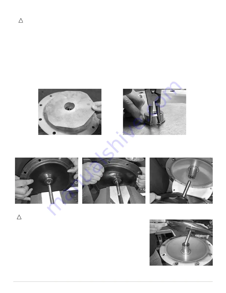
2. There are no special tools required to install the new backup diaphragm. Secure the shaft in a vise with soft jaws. Apply medium
strength thread locker (Loctite® 243 or equivalent) to the threads on the new backup diaphragm. Gently screw the diaphragm
threads into the shaft with two hands and stop when hand tight. Remove the diaphragm and shaft from the vise, and insert the
shaft into the automatic valve.
Reassembly
1. If removed on disassembly, reinstall the backup plate. Clean and dry the internal housing surface, taking particular care to ensure
the flange area is completely clean and dry. Slide the backup plate onto the non-wetted housing until it rests on the retaining ring.
Reinstall the retaining ring using snap ring pliers.
IMPORTANT!
When replacing dampener diaphragms the automatic valve must
be tested for proper function before dampener is reassembled.
3. Before proceeding with reassembly, test the automatic valve to ensure proper operation.
a. With air off, attach a compressed air line to the air inlet port on the top of the
dampener.
b. Place the non-wetted housing in a vise with soft jaws.
c. Push the diaphragm and shaft into the automatic valve until it stops. Turn on
air supply. Compressed air should now be flowing into the air chamber. If there
is no air flow, one or more O-rings are installed in the wrong groove.
d. Pull the shaft part way out of the automatic valve. Compressed air should stop
flowing. If air flow does not stop, one or more O-rings are installed in the wrong
groove.
e. Remove the compressed air line from the dampener, and the non-wetted
housing from the vise.


