104-A00 Page 5/12
OPERATION
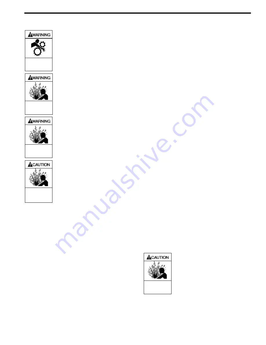
Operation without guards in place can
cause serious personal injury, major
property damage, or death.
Do not operate
without guard
in place
Disconnecting fluid or pressure
containment components during pump
operation can cause serious personal
injury, death or major property damage
Hazardous pressure
can cause personal
injury or property
damage
Failure to relieve system pressure prior
to performing pump service or
maintenance can cause personal injury
or property damage.
Hazardous pressure
can cause personal
injury or property
damage
Pumps operating against a closed valve
can cause system failure, personal
injury and property damage
Hazardous pressure
can cause personal
injury or property
damage
PRE-START UP CHECK LIST
1. Check the alignment of the pipes to the pump. Support
pipes so that they do not spring away or drop down when
pump flanges or union joints are disconnected.
2. Verify proper coupling alignment.
3. Blackmer helical gear reducers (if supplied) are shipped
from the factory without oil in the gearcase. Fill with the
grade of oil indicated on the reducer tag. For more
specific instructions on Blackmer gear reducers, refer to
the appropriate Gear reducer Installation, Operation and
Instruction Manual.
4. Check the entire pumping system to verify that the
proper inlet and discharge valves are fully open, and that
the drain valves and other auxiliary valves are closed.
5. Install vacuum and pressure gauges on the pump in the
connections provided. These can be used to check
actual suction and discharge conditions after pump start-
up.
6. Check the wiring of the motor, and briefly turn on the
power to make sure that the pump rotates in the
direction of the rotation arrow.
START UP PROCEDURES
NOTICE:
Consult the "General Pump Troubleshooting" section of
this manual if experiencing difficulties during start up.
1. Start the motor. Priming should occur within one minute.
2. Check the vacuum and pressure gauges to see if the
pump is operating within the expected conditions.
3. Check for leakage from the piping and equipment.
4. Check for overheating, excessive noise or vibration of
the pump, reducer, and motor.
5. Check the flow rate to ensure the pump is operating
within the expected parameters. Record flow rate in the
"initial Start Up Information" section.
6. Check the pressure setting of the relief valve by briefly
closing a valve in the discharge line and reading the
pressure gauge. This pressure should be 20 psi (1.4 bar)
higher than the maximum operating pressure.
CAUTION: Do not run the pump for more than 15
seconds with the discharge valve completely closed.
If adjustments need to be made, refer to "Relief Valve
Setting & Adjustment."
Incorrect settings of the pressure relief
valve can cause pump component
failure, personal injury, and property
damage.
Hazardous pressure
can cause personal
injury or property
damage


