


1901-a00
18
LASER ALIGNMENT METHOD
The laser alignment method is preferred for checking alignment.
Laser alignment is usually the most accurate method. Follow the laser alignment equipment manufacturer’s instructions for this method.
As previously mentioned, pump and motor shafts need to be in alignment while they are at their intended operating temperature.
When the shafts are aligned “cold” (at ambient temperature), we will intentionally position the motor shaft up or down in vertical
parallel alignment to allow for thermal growth. Then, when the alignment is checked “hot” (at stable operating temperature), the shafts
should be confirmed to be in alignment. Use the values in the following table as a starting point for cold alignment settings. The actual
cold alignment setting will be determined after the hot alignment is performed.
COLD SETTING OF PARALLEL VERTICAL ALIGNMENT
PUMPAGE TEMPERATURE
SET DRIVER SHAFT
10°C (50°F)
0.051 mm (0.002") LOW
66°C (150°F)
0.025 mm (0.001") HIGH
121°C (250°F)
0.127 mm (0.005") HIGH
177°C (350°F)
0.229 mm (0.009") HIGH
232°C (450°F)
0.330 mm (0.013") HIGH
260°C (500°F)
0.432 mm (0.017") HIGH
PRESSURE RELIEF VALVES
E Series pumps are positive displacement pumps, which means the system must have provisions for pressure relief
protection, such as a relief valve mounted directly on the pump or in-line with the system. Alternatively, the system can be
installed with a torque-limiting device or a rupture disk.
If the system requires the pump to operate in both directions, pressure relief protection is required on both sides of pump.
When using an integral relief valve, the adjusting screw cap must always point towards the suction side of pump. If shaft
rotation has to be reversed, simply remove the pressure relief valve and reinstall it in the proper configuration to avoid
over-pressurization of the system.
Pressure relief valves are not intended to control pump flow or regulate discharge pressure.
The pump-mounted integral relief valve should never be relied upon for system protection.
PUMP CONDITION MONITORING
There are several pump conditions that can be monitored.
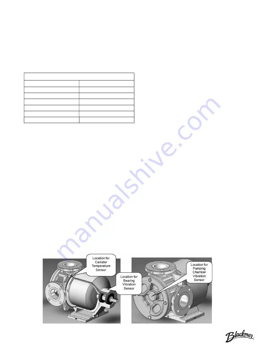
Canister Temperature:
Heat is generated in the canister when the pump is running because of moving magnetic fields
that pass through it. The pump has an internal cooling path that pulls heat away from the canister. If this cooling path is
obstructed, the canister and magnet could become very hot, which could damage the magnets and/or canister O-ring.
The canister temperature can be monitored with a temperature probe attached to the access port in the magnet housing
near the casing.
Bearing Vibration:
The pump shaft is supported by rolling-element bearings. The condition of the bearings can be
monitored with a vibration sensor attached to the magnet housing near the bearings.
Pumping Chamber Vibration:
The pumping gears rotate with the casing and are supported by journal bushings. The
condition of gears and bushings can be monitored with a sensor attached to the pump head.
OPTIONAL SENSOR LOCATIONS
OPTIONAL SENSOR LOCATIONS
Содержание IOM E Series
Страница 9: ...1901 a00 9 TEMPERATURE RATINGS...
Страница 10: ...1901 a00 10 MAGNETIC COUPLING STRENGTHS...
Страница 49: ...1901 a00 49 Notes...
Страница 50: ...1901 a00 50 Notes...