background image

Part 

II: 

Setting  Up 

The 

Log 

Splitter 


instructions. 

Make  sure  all  bolts  and  nuts  are  fitted 

correctly  and  tightened  when  assembling  the  machine.


When opening the wooden box, beware of sharp edges on 
the closing mechanisms. 


Please  observe  the  following  when  beginning  machine 

assembly: 


Clear  the  area  of  nearby  persons,  particularly 
children. 


Use a forklift or similar device to move or lift the 
pallet/machine. 


Keep the load close to the ground. 


Move the machine to the assembly site. 


Ensure there is enough room to safely assemble the 
machine and access the machine from all sides. 


1.


Removing the transport packaging 


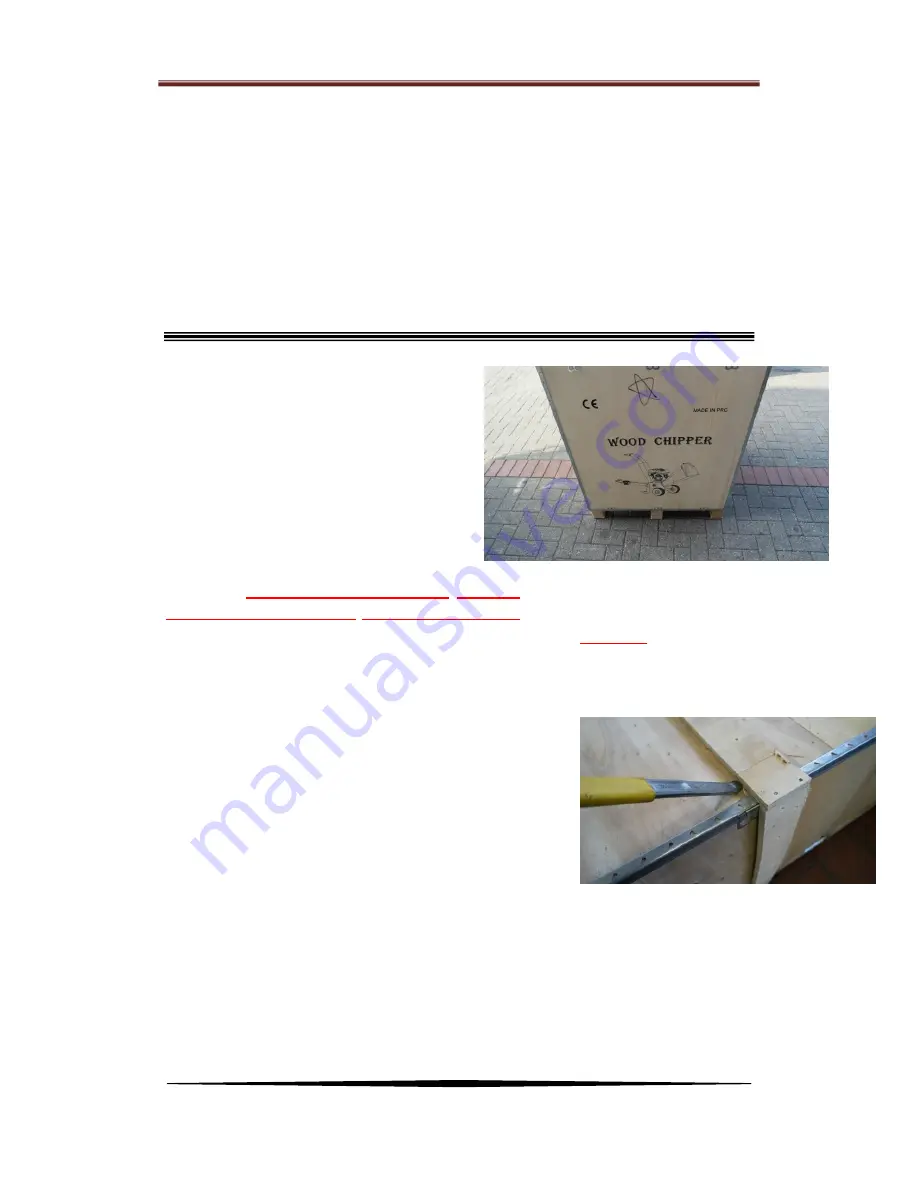
Remove the transport packaging as shown in Figures 1 to 4 

(may vary). 


Read  the  entire  assembly  instructions 

BEFORE! assembling the wood chipper 
and  familiarise  yourself  with  the 
individual assembly steps! 


Fig. 2 Attaching the arm 


PART III: Assembly instructions 


The machine is delivered from the factory in 


the 


transport 


configuration. 


Always 


use 


tools, 


appliances, 


and 


lifting 


equipment 


of 


suitable 


size 


and 


po


wer 


for 


assembly. 


2


people are always required to lift, move, and 


assemble 


the 


machine. 


Wear 


adequate 


protective clothing such as safety shoes and 


protective gloves. Please observe the safety 


precautions 


specified 


in 


“General 


Safety 


Instructions” 


chapter 


of 


these 


operating 


Fig. 1 GTS-2000 inside transport packaging 


Содержание GTE-2000

Страница 1: ...GTE 2000 WOOD CHIPPER Instruction Manual Table of Contents ...

Страница 2: ...avoided could result in minor or moderate injury This information is important in proper using of your machine Failure to follow this instruction could result in damage to your machine or property Additional Information and Potential Changes We reserve the right to discontinue change and improve its products at any time without notice or obligation to the purchaser The descriptions and specificati...

Страница 3: ...Part I GeneralSafety Rules 2 Safety Labels Found on Your Unit ...

Страница 4: ...perators must be fully trained before using this machine B User Manual is read and understood C Machine is positioned on level ground all guards are fitted and in good condition D Blades are in good condition and secure All blades are sharpened or replaced in sets E All fasteners are checked for tightness F Only WOODEN materials free of nails etc are fed into the machine G Fire extinguisher is ava...

Страница 5: ...hich can catch on moving parts D We recommend wearing gloves while using the Wood Chipper Be sure your gloves fit properly and do not have loose cuffs or drawstrings E Wear shoes with non slip treads when using your Wood Chipper If you have safety shoes we recommend wearing them Do not use the machine while barefoot or wearing open sandals F Wear long pants while operating the Wood Chipper G Keep ...

Страница 6: ... vapours have dissipated Wipe up any spilled fuel to prevent a fire hazard and properly dispose of the waste F Allow the engine to cool completely before storing in any enclosure Never store a machine that has gas in the tank or a fuel container near an open flame or spark such as a water heater space heater clothes dryer or furnace G Never make adjustments or repairs with the engine running Shut ...

Страница 7: ...ect for damage Vibration is generally a warning of trouble Check damaged parts and clean repair and or replace as necessary H Never tamper with safety devices Check their proper operation regularly I Before performing any maintenance or inspection procedure shut down the engine disconnect the spark plug wire keeping it away from the spark plug to prevent accidental starting wait 5 minutes for mach...

Страница 8: ...tart Electric Start Engine 13HP 15HP four strokes 13HP 15HP four strokes Power Gasoline petrol Gasoline petrol Chipper Capacity 4CBM hour to 6CBM hour 4CBM hour to 6CBM hour Wood Diameter diameter 120mm diameter 120mm Permitted wood width 310mm 310mm Chipper Blade twin reversible blades twin reversible blades Tire 6 5 8 4 0 8 4 8 8 6 5 8 4 0 8 4 8 8 Overall Height 1150mm 1150mm Overall Length 1800...

Страница 9: ...from all sides 1 Removing the transport packaging Remove the transport packaging as shown in Figures 1 to 4 may vary Read the entire assembly instructions BEFORE assembling the wood chipper and familiarise yourself with the individual assembly steps Fig 2 Attaching the arm PART III Assembly instructions The machine is delivered from the factory in the transport configuration Always use tools appli...

Страница 10: ...e The transport box may contain more bolts nuts washers etc than required for initial assembly This is intentional and not a defect in quality A bolt for the sheet is normally included as a spare The feather key is installed and only included as a spare part to connect the centrifugal clutch to the engine shaft If the feather key is required it must be shortened to the corresponding length Attenti...

Страница 11: ...mal safety precautions Adjust the stand so that it is in the position shown in Figure 9 and secure the stand again using the split pin Then loosen the four bolts attach the stand and screw it back on tightly pin Fig 11 Removed bolts arrangement Fig 10 Loosening bolts attachment to housing Fig 5a Feather key as a spare part Fig 8 Scope of delivery discharge chute Fig 9 Adjusting and securing using ...

Страница 12: ...el The right side is mounted accordingly Loosen the bolts and attach the wheel in the correct direction the axle is pointing down the connecting flange up Tighten the bolts again and proceed in the same manner for the other wheel Fig 12 Correct fit of the stand Fig 15 Loosening the 4 bolts Fig 16 Correct fit of the wheel Flange on the Wheel axle on ...

Страница 13: ...he belt pulley cover and grease the shaft Remove the four bolts on the cover and set the cover and bolts aside for the time being Then grease the shaft on the grease nipples Fig 22 and 23 Fig 14 Wheels Fig 18 Assembled wheels and stand Fig 20 Loosening bolts on the right ...

Страница 14: ...nd shift the engine on the housing to adjust the belt pulley correctly and flush This is important because otherwise the V belts do not correctly correspond to their function and can wear quickly If the alignment is correct tighten the bolts again Bear in mind that the engine block is made of aluminium and the bolts should not be tightened too severely Fig 22 Grease nipple shaft belt pulley Fig 24...

Страница 15: ...ey alignment Figures 28 and 29 show the bolts to be loosened To adjust the tension loosen the lock nuts and twist the adjusting screws see Figure 30 Depending on the rotation of the bolt the engine plate moves upwards or downwards in the slot and the belts are tensioned or loosened After a successful correct alignment screw the lock nuts back on again and Fig 26 Loosen slightly then shift engine F...

Страница 16: ...Part II Setting Up The Log Splitter 15 tighten the plate again using the four bolts ...

Страница 17: ...nylon nuts and bolts 9 Attaching the feed hopper and wiring the safety switch Attach the feed hopper as shown in Figures 38 to 42 and Fig 31 Chute parts Fig 35 Upper chute part Fig 32 Loosen four bolts Fig 36 Rotatable upper chute part Fig 33 Screw on bottom chute part Fig 37 Adjusting the discharge range ...

Страница 18: ... Splitter 17 install the cable connection for the kill switch Fig 38 Feed hopper The RED bar located in the picture is the kill switch Fig 42 Connection assembly for kill switch Fig 39 Loosen two bolts Fig 40 Installed feed hopper ...

Страница 19: ...e Log Splitter 18 10 Assembling the drawbar Then assemble the drawbar as shown in Figures 43 to 45 Loosen both bolts attach the drawbar and tighten them again Fig 43 Drawbar Fig 45 Assembled drawbar Fig 44 Loosen two bolts ...

Страница 20: ... many bolts included You can keep it as a spare Fig 46 Guard and bolts Fig 48 Attached guard 12 Assembling the exhaust baffle Attach the baffle as shown in Figures 49 to 51 Make sure the exhaust fumes are directed to the side as shown in Figure 51 to avoid burns in the event of bending over the machine Fig 47 Correct arrangement in the back ...

Страница 21: ...nstructions Fig 49 Baffle and bolts Fig 50 Exhaust pipe Fig 51 Assembled baffle 13 Opening the feed hopper The hopper can be opened and tilted to the side for maintenance work Never conduct maintenance work while the machine is or blades are running and make sure that the machine is completely switched off before opening the hopper ...

Страница 22: ...the engine manual Make sure the wood chipper is correctly aligned horizontally before filling it with oil The engine has 2 filler necks You can see the rear filler neck in Figure 59 Pour in oil until it becomes visible in the upper section of the filler neck i e just below overflow point After filling close the filler neck by turning the cap Then fill normal petrol into the tank Fig 59 Filler neck...

Страница 23: ...e Move the switch to the On position Open the choke and fuel tap Move the throttle to the centre position and start the engine using the recoil starter When the engine is running put the choke back to the closed position Choke Fuel tap Fig 62 Choke and fuel shut off label Fig 61 Engine has an electric start turn key to start Fig 64 Throttle Fig 65 Recoil starter and electric start Engine name JIAN...

Страница 24: ...x Part II Setting Up The Log Splitter 23 Fig 63 Open choke and fuel shut off Choke Fuel tap ...

Страница 25: ...oose cuffs and steel toed shoes D Knowing the correct and incorrect methods of Chipping woods Never using an incorrect or unsafe method Starting 1 Position your Wood Chipper on flat dry ground and then stop the front wheel with brake make sure the machine cannot be moved 2 Make sure the fuel shut off valve is in the ON position 3 Move the choke control lever to the CHOKE position should only be ne...

Страница 26: ... OFF position Operator Zone Wood Chipping NOTICE Woods and branches diameter should be no bigger than 120mm Do not place your hands into the chute when loading This is a very UNSAFE method and could result in injury to your hands Do not reach or step across the rail while the Wood Chipper is running This is a very UNSAFE method which could cause personal injury even death WARNING ...

Страница 27: ... procedures Before performing any maintenance procedure or inspection stop the engine wait five minutes to allow all parts to cool Disconnect the spark plug wire keeping it away from the spark plug Disconnect the Battery Terminals Electric start only Regular Maintenance Checklist Procedure Before Each Use Every 3 Hours Every 25 Hours Every 100 Hours Check engine oil level Δ Check general equipment...

Страница 28: ...maintenance 10 Part IV Maintaining The Wood Chipper Lubrication All Bearings of your Chipper are sealed units a nd should have sufficient lubricant to last the life of your machine with normal use Greasing the rack and Pinion NOTICE All the rack and pinion should be greased before every use NOTICE ...

Страница 29: ...y or cracked change it If it s oily leave it out hold a rag over the plug hole and pull the recoil cord several times to blow out any oil in the cylinder then wipe off the plug and reinsert it The engine lacks power or is not running smoothly Please refer to the engine user manual for engine specific procedures Check that the Throttle Lever is in the Run position Is the air filter clean If it s di...

Страница 30: ...rty Operator Lever Snapping out of gear or not staying in gear Lever not all the way forward when rack comes under full load Push lever quicker and more forcefully into the full forward position Ram has been overloaded at lower part of face Check gear for straightness Machine does not seem to have full chipping power The belts may be too loose and slipping Adjust or replace belts as needed Operato...

Страница 31: ...itch 4 wheel 20 Discharge chute 5 Belt cover inner plate 21 Chute adjust 6 clutch 22 Engine fixation 7 bearing 23 In feed 8 pulley 24 Belt 9 42 9 5 spacer 25 Rubber plate 10 Belt cover 26 Rubber fixation upper 11 Bearing fixation frame 27 Rubber fixation side 12 roller 28 chain 13 Rubber pad 29 Lower blade 14 Support feet 30 On off switch 15 axis 31 Engine 16 Pin ...

Страница 32: ...Part V Troubleshooting and Parts List 31 SUPPLIED BY BLACKTOOLS UNIT 10 HEDGEND INDUSTRIAL ESTATE CT7ONB BIRCHINGTON FOR SPARE PARTS AND SERVICES PLEASE CALL 01795500077 ...

Отзывы: