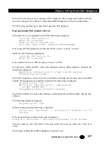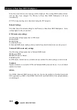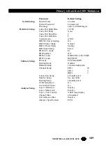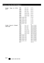
113
Primary to Basic Rate ISDN Multiplexer
TECHNICAL: 0118 931 2233
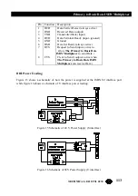
Pin Function Description
1
DCD
Data Carrier Detect (always active)
2
RXD
Received Data (output)
3
TXD
Transmitted Data (input)
4
DTR
Data Terminal Ready (input- ignored)
5 GND Ground
6
DSR
Data Set Ready (always active)
7
RTS
Request to Send (input- active to
allow
The Primary to Basic Rate
ISDN Multiplexer
to send Data )
8
CTS
Clear to Send ( output- active when
The Primary to Basic Rate ISDN
Multiplexer
can receive Data )
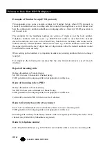
BRI Power Feeding
Figure 15 shows a schematic of how the power is supplied at the ISDN S0 interface port
while figure 16 shows a schematic of U interface power feeding.
Figure 15 Schematic of 40 V Power Supply (S interface)
Figure 16 Schematic of 88V Power Supply (U interface)

