Customer Service Information
Call: (724) 746-5500
Phone orders 24 hours a day, 7:00 AM Monday to
midnight Friday; 8:00 AM to 4:00 PM Saturday (EST)
Fax: (724) 746-0746
or in North America
1-800-321-0746
Mail order:
Black Box Corporation, 1000 Park Drive, Lawrence, PA
15055-1018
Technical Support and fax orders 24 hours a day
Federal Communications Commission Radio Frequency Interference Statement
This equipment generates, uses, and can radiate radio frequency energy that may cause interference to
radio communication if not installed and used in strict accordance with the manufacturer’s instructions. It
has been tested and found to comply with the limits for a Class A computing device in accordance with the
specifications in Subpart J of Part 15 of FCC rules, which are designed to provide reasonable protection
against such interference when the equipment is operated in a commercial environment. Operation of this
equipment in a residential area is likely to cause interference, in which case the user at his own expense will
be required to take whatever measures may be necessary to correct the interference.
Changes or modifications not expressly approved by the party responsible for compliance could void the
user’s authority to operate the equipment.
This digital apparatus does not exceed the Class A limits for radio noise emission from digital apparatus
set out in the Radio Interference Regulation of the Canadian Department of Communications.
Le présent appareil numérique n’émet pas de bruits radioélectriques dépassant les limites applicables aux
appareils numériques de classe A prescrites dans le Règlement sur le brouillage radioélectrique publié par le
ministère des Communications du Canada.
Safety Certifications
UL:
Listed to UL1950 and CSA 22.2, No. 950, Safety of Information Technology
Equipment, Including Electrical Business Equipment.
TUV/GS:
Certified to EN 60 950, Safety of Information Technology Equipment, Including
Electrical Business Equipment.
CE:
The products described herein comply with the Council Directive on
Electromagnetic Compatibility (89/336/EEC) and the Council Directive on Electrical
Equipment Designed for use within Certain Voltage Limits (73/23/EEC). For further
details, contact Black Box Corporation.
NOTE: Modules are FCC approved and UL, TUV/GS and CE certified when installed in a Black Box chassis only.
1000 Park Drive • Lawrence, PA 15055-1018 USA
TEL: (724) 746-5500 • FAX: (724) 746-0746
EMAIL: [email protected]
WEB: http://www.blackbox.com
© 1992 - 2001 Black Box Corporation. All rights reserved.
The information in this document is subject to change without notice. Black Box Corporation assumes no responsibility for any
errors that may appear in this document. Specific brands and product names may be trademarks and are the property of their
respective companies.
Document Number 51-80780BB-00 D2
November 2001
12
11
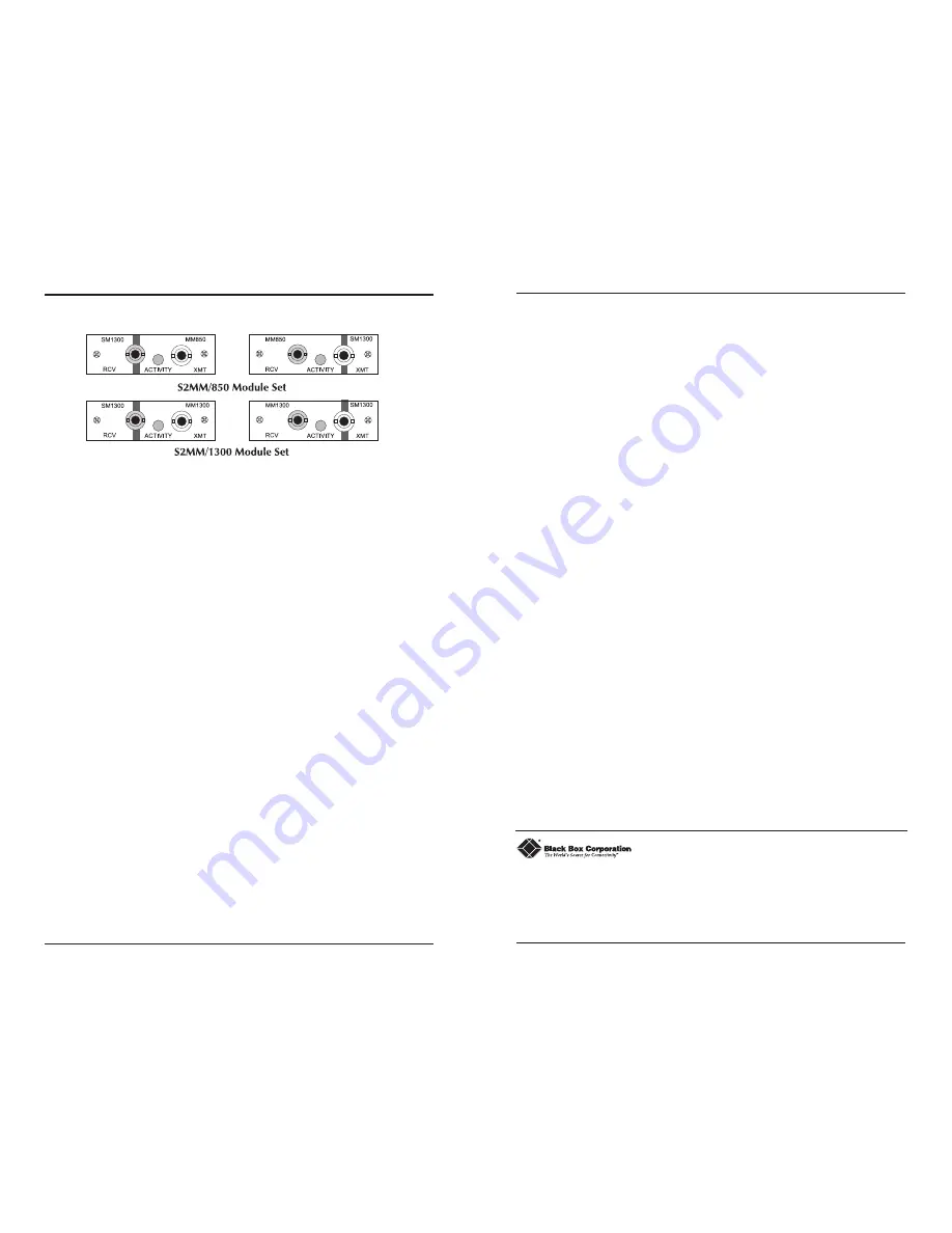
LEDs on S2MM
The following diagram shows the LEDs on an
S2MM:
Each module in
S2MM Module Sets
has one Activity LED. This LED
glows green in normal operation.
Fiber Optic Cleaning Guidelines
Fiber optic transmitters and receivers are extremely susceptible to contamination by
particles of dirt or dust which can obstruct the optic path and cause performance degradation.
Good system performance requires clean optics and connector ferrules.
1) Use fiber patch cords (or connectors, if you terminate your own fiber) only from a
reputable supplier; low quality components can cause many hard-to-diagnose problems
in an installation.
2) Dust caps are installed at the factory to ensure factory-clean optical devices. These
protective caps should not be removed until the moment of connecting the fiber cable to
the device. Assure that the fiber is properly terminated, polished and free of any dust or
dirt and that the location is as free from dust and dirt as possible.
3) Store spare caps in a dust free environment such as a sealed plastic bag or box so that
when reinstalled they do not introduce any contamination to the optics.
4) Should it be necessary to disconnect the fiber device, reinstall the protective dust caps.
5) If you suspect that the optics have been contaminated, alternate between blasting with
clean dry compressed air and flushing with methanol to remove particles of dirt.
Electrostatic Discharge Precautions
Electrostatic discharge (ESD) can cause damage to your add-in modules. Always observe
the following precautions when installing or handling an add-in module or any board assembly.
1) Do not remove unit from its protective packaging until you’re ready to install it.
2) Wear an ESD wrist grounding strap before handling any module or component. If you do
not have a wrist strap, maintain grounded contact with the system unit throughout any
procedure requiring ESD protection.
WARNING! Integrated circuits and fiber optic components are extremely susceptible to
electrostatic discharge damage. Do not handle these components directly unless you are
a qualified service technician and use tools and techniques that conform to accepted
industry practices.
3) Hold boards by the edges only; do not touch the electronic components or gold
connectors.
4) After removal, always place the boards on a grounded, static free surface, ESD pad or in a
proper ESD bag. Do not slide the board over any surface.


