11
CHAPTER 3: Configuration and Installation
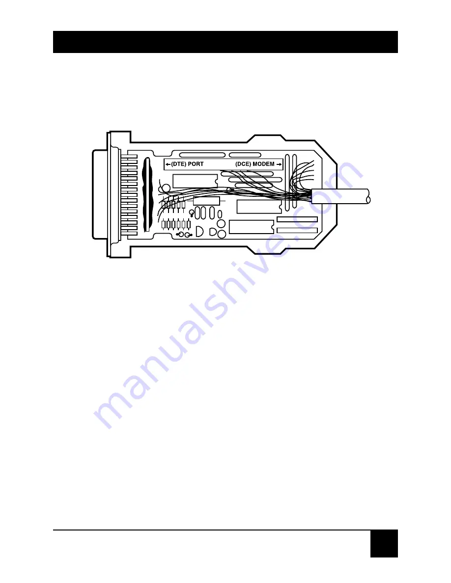
The converter is factory-strapped for V.24 DTE/V.35
DCE as shown in Figure 2.
Figure 2. V.24 DTE , V.35 DCE.
To configure the cable for V.35 DTE/V.24 DCE, follow
these steps:
1. Locate the RS-232 connector on the cable.
2. To remove the cover of the connector, press in on the
four tabs located on each side of the connector and lift
the top half of the cover from the bottom half.
3. Locate the 40-pin DTE/DCE socket on the connector
circuit board. Figure 2 illustrates the board’s factory
configuration.


