background image

31

1.877.877.2269

BLACKBOX.COM

NEED HELP?

LEAVE THE TECH TO US

LIVE 24/7

TECHNICAL

SUPPORT

1.877.877.2269

CHAPTER 8: FIRMWARE UPGRADE THROUGH USB PORT

-The matrix switcher has a USB port for online firmware upgrade on the front panel.
Follow these steps to upgrade firmware:
STEP 1: Copy the upgrade software and the latest upgrade file (.bin) to PC.
STEP 2: Connect the USB ports of the matrix switcher and the PC via USB cable.
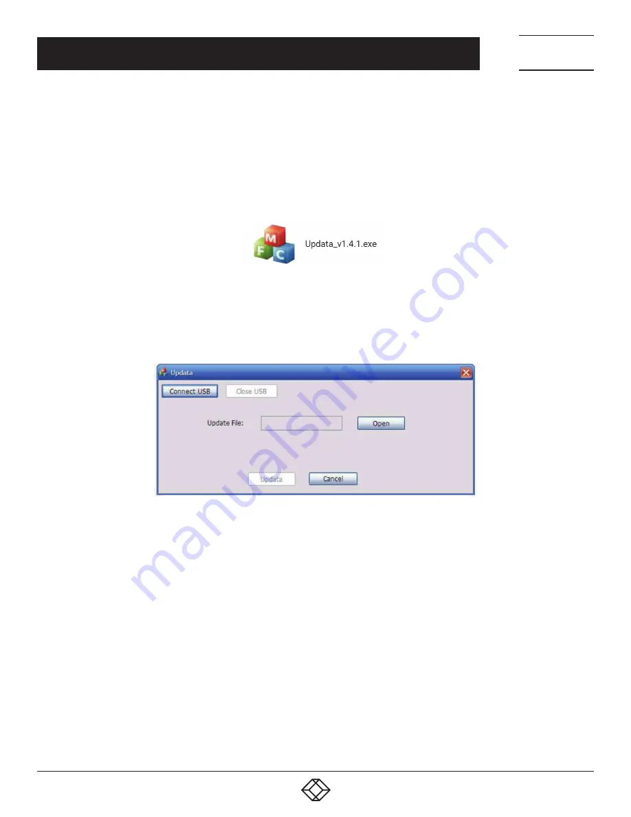
STEP 3: Double-click the update software icon (see below).

FIGURE 8-1. UPDATE SOFTWARE ICON

It will enter the upgrade interface shown below.

FIGURE 8-2. UPGRADE INTERFACE

STEP 4: Click Connect USB.
STEP 5: Click Open to load the upgrade file, then click Update to start firmware upgrading.
NOTE: To ensure available control, the COM number of the PC should be 1–9.

Содержание AVS-HDMI2-8X8

Страница 1: ...24 7 TECHNICAL SUPPORT AT 1 877 877 2269 OR VISIT BLACKBOX COM VIDEO MATRIX SWITCHER 8X8 HDMI 2 0 AVS HDMI2 8X8 USER MANUAL 1 2 3 4 5 6 SYSTEM MONITOR FIRMWARE IR 7 8...

Страница 2: ...TON CONTROL 11 4 1 I O Connection Switching 11 4 2 EDID Configuration 11 4 3 I O Connection Inquiry 11 5 IR CONTROL 12 6 RS 232 CONTROL 13 6 1 Installation Un installation of RS 232 Control Software 1...

Страница 3: ...Setting 27 7 3 6 Network Configuration 28 7 3 7 Password Modification 29 7 4 TCP IP Configuration 29 7 5 GUI Update 30 8 FIRMWARE UPGRADE THROUGH USB PORT 31 9 DIMENSIONAL DRAWING 32 10 TROUBLESHOOTIN...

Страница 4: ...zard do not expose the unit to rain moisture or install this product near water Do not put any heavy items on the extension cable in case of extrusion Do not remove the housing of the device as openin...

Страница 5: ...rol Connector 1 3 5 mm mini jack 1 RJ 45 female 1 3 pin pluggable terminal block Video Signal HDMI 2 0 and HDCP 2 2 Audio Signal Dolby Digital DTS DTS HD Power AC Adapter Input Power 100 to 240 VAC 50...

Страница 6: ...gnals Supports HDMI 2 0 HDCP 2 2 compatible and is backward compatible to the earlier versions Transmits 4K x 2K 60 Hz 4 4 4 signal up to 16 4 feet 5 m via HDMI port Provides powerful EDID management...

Страница 7: ...URE 2 1 FRONT PANEL TABLE 2 1 FRONT PANEL COMPONENTS NUMBER IN FIGURE 2 1 COMPONENT DESCRIPTION 1 Firmware USB port for firmware upgrading 2 Power LED Lights red when power is ON Turns green in standb...

Страница 8: ...source device 2 Outputs SPDIF 8 audio output ports for de embedded HDMI audio HDMI 8 HDMI Output ports connect to HDMI displays 3 Control EDID 4 pin EDID DIP switches set EDID data 1 ON 0 OFF Refer to...

Страница 9: ...clean environment with proper temperature and humidity All of the power switches plugs sockets and power cords should be insulated All devices should be connected before power on 3 2 SYSTEM DIAGRAM Th...

Страница 10: ...serial control STEP 5 Insert an IR receiver to the IR IN port to control this switcher via IR Remote STEP 6 Connect the TCP IP ports of control device e g Laptop and the switcher to enable TCP IP cont...

Страница 11: ...f immediately 4 2 EDID CONFIGURATION The rear panel has a 4 pin EDID DIP switcher to manage EDID The EDID data and its corresponding DIP switcher status are shown in the next table TABLE 4 1 EDID DATA...

Страница 12: ...ons same with the corresponding front panel buttons 3 OUTPUTS Output channel selection buttons same with the corresponding front panel buttons 4 Menu buttons ALL Select all inputs outputs To convert a...

Страница 13: ...files in corresponding file path 6 2 BASIC SETTINGS Connect the splitter to the necessary input devices and output devices Then connect it with a PC installed RS 232 control software Double click the...

Страница 14: ...ate 9600 Data bit 8 Stop bit 1 Parity bit None 6 3 1 SYSTEM COMMANDS TABLE 6 1 SYSTEM COMMANDS COMMAND FUNCTION FEEDBACK EXAMPLE Type Query the model AVS HDMI2 8X8 Version Query the version of firmwar...

Страница 15: ...respectively like 1 1 2 2 All Through All Switch off all the output channels All Closed x Transfer signals from the input channel x to the output channel x x 1 8 04 Through x Switch off the output ch...

Страница 16: ...Query the I O connection status Out 01 02 03 04 In 03 03 03 03 Out 05 06 07 08 In 03 03 03 03 9976 Query the output resolution Resolution Out 1 3840x2160P Out 2 3840x2160P Out 3 3840x2160P Out 4 3840x...

Страница 17: ...the EDID data is available and the audio part supports not only PCM mode then force set it to support PCM mode only If the EDID data is not available then set it as initialized EDID data EDIDH x B y E...

Страница 18: ...S COMMAND FUNCTION FEEDBACK EXAMPLE DigitAudioON x Enable SPDIF audio output port x X 1 8 enable the port x X 9 enable all ports DigitAudio ON with x ALL Outputs DigitAudioOFF x Disable SPDIF audio ou...

Страница 19: ...ort cannot be changed Controlled by single PC Connect a computer to the TCP IP port of the switcher and set its network segment to the same as the default IP of the switcher 192 168 0 178 FIGURE 7 1 M...

Страница 20: ...the Ethernet port of the PC with twisted pair STEP 2 Set the PC s network segment to the same as the the Switcher Remember the PC s original network segment STEP 3 Set the Switcher s network segment t...

Страница 21: ...NTROL Example of TCPUDP software 1 Connect a computer with TCPUDP software to the Switcher Open the TCPUDP software or any other TCP IP communication software and create a connection enter the IP addr...

Страница 22: ...e in your PC and click the icon as below PCs running Windows XP may have issues in finding the UPnP icon Follow these steps to switch on UPnP protocol 1 Add UPnP component go to Control Panel double c...

Страница 23: ...mode User name user Password user default setting NOTE Log in as admin can access more configuration interfaces than user Here is a brief introduction to the interfaces 7 3 1 SCENE SETTING Type the u...

Страница 24: ...every possible connection between every input and output Users can carry out the connections by clicking the corresponding button Buttons 1 8 at the bottom right corner provide quick saving and recall...

Страница 25: ...IP CONTROL 7 3 3 EDID CONFIGURATION 1 Click the Setting button to enter the configuration interface FIGURE 7 8 EMBEDDED EDID All embedded EDID of the switcher are shown in the above interface Users ca...

Страница 26: ...elect one OUTPUT device to copy its EDID STEP 2 Select one or more input devices that need to add EDID When To All inputs is selected all input devices will copy the EDID from the output device STEP 3...

Страница 27: ...TROL 7 3 5 STATUS SETTING Product Name and Model Click Status to enter the following interface to modify the name and mode of this machine This will display on the switcher s LCD screen FIGURE 7 11 ST...

Страница 28: ...P IP CONTROL Scene name Select Scene to enter the following interface to modify the name of scenes FIGURE 7 13 STATUS SCENE 7 3 6 NETWORK CONFIGURATION Click Network to enter the following interface t...

Страница 29: ...hine they cannot be operated 7 4 TCP IP CONFIGURATION IP address subnet mask and Gateway of the switcher can be modified via GUI from the above description but beyond that users can configure the IP p...

Страница 30: ...pdate in http 192 168 0 178 100 Type the username and password the same as the GUI log in settings modified password will be available only after rebooting to log in the configuration interface After...

Страница 31: ...e upgrade software and the latest upgrade file bin to PC STEP 2 Connect the USB ports of the matrix switcher and the PC via USB cable STEP 3 Double click the update software icon see below FIGURE 8 1...

Страница 32: ...32 1 877 877 2269 BLACKBOX COM NEED HELP LEAVE THE TECH TO US LIVE 24 7 TECHNICAL SUPPORT 1 877 877 2269 CHAPTER 9 DIMENSIONAL DRAWING FIGURE 9 1 DIMENSIONAL DRAWING...

Страница 33: ...IR receiver 1 Replace the battery 2 Contact Black Box Technical Support at 877 877 2269 or info blackbox com 3 Adjust the distance and angle and point right at the IR receiver Power Indicator remains...

Страница 34: ...correct the interference by one of the following measures Reorient or relocate the receiving antenna Increase the separation between the equipment and receiver Connect the equipment into an outlet on...

Страница 35: ...tes que impidan el flujo de aire por los orificios de ventilaci n 10 El equipo el ctrico deber ser situado fuera del alcance de fuentes de calor como radiadores registros de calor estufas u otros apar...

Страница 36: ...e consequential or cost of cover damages resulting from any errors in the product information or specifications set forth in this document and Black Box Corporation may revise this document at any tim...

Страница 37: ...__ _ _________________________________________________________________________________________________ _________________________________________________________________________________________________...

Страница 38: ...__ _ _________________________________________________________________________________________________ _________________________________________________________________________________________________...

Страница 39: ..._______ _ _________________________________________________________________________________________________ ____________________________________________________________________________________________...

Страница 40: ...NEED HELP LEAVE THE TECH TO US LIVE 24 7 TECHNICAL SUPPORT 1 877 877 2269 COPYRIGHT 2018 BLACK BOX CORPORATION ALL RIGHTS RESERVED AVS HDMI2 8X8_USER_REV1 PDF...

Отзывы: