background image


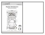
DUAL DISPLAY L/C/R METER 
 

INSTRUCTION MANUAL 


Model-A = 879 

Model-B = 878A 


Содержание 878A

Страница 1: ...INSTRUCTION MANUAL MANUAL DE INSTRUCCI NES Dual Display LCR Meter Model 878A 879 Medidor LCR de Doble Exhibicion Visual Modelos 878A 879...

Страница 2: ...1 DUAL DISPLAY L C R METER INSTRUCTION MANUAL Model A 879 Model B 878A...

Страница 3: ...on Factor Quality Factor Phase Angle 13 Test Frequency 14 L C R function selector 14 Relative 14 Tolerance 14 Auto manual ranging 15 Automatic Fuse Detection 15 Parallel Series Mode 15 Calibration 16...

Страница 4: ...be followed to ensure safe operation as well as to maintain the meter in a safe condition Some common international electrical symbols used in this manual are shown below Table DC Direct Current See...

Страница 5: ...first de energize the circuits before connecting to the test leads Discharge capacitor before testing The meter is safety certified in compliance with EN61010 IEC 1010 1 Installation Category II CAT...

Страница 6: ...nd manual ranging Front panel pushbuttons maximize the convenience of function and feature selection such as data hold maximum minimum and average record mode relative mode tolerance sorting mode freq...

Страница 7: ...election button Parallel and series mode selection button 7 Tolerance mode selection button 8 Data hold Maximum Minimum and Average reading selection button 9 Range selection button 10 Relative mode a...

Страница 8: ...mode indicator 6 MIN Minimum reading indicator 7 DH Data hold indicator 8 Phase angle indicator Model A only 9 Q Quality factor indicator 10 D Dissipation factor indicator 11 Secondary display 12 Bee...

Страница 9: ...or 22 SER Series mode indicator 23 Mk Resistance Ohm indicator 24 Inductance Henry indicator 25 Capacitance Farad indicator 26 RS232 indicator Special Indication Characters Indicates short connectors...

Страница 10: ...cleaned regularly Do not leave the instrument exposed to direct heat from the sun or beat source for long periods Before removing the cover ensure that the instrument is disconnected from any circuit...

Страница 11: ...uctor into component receptacle socket or connect the test clip to the component leads as required 4 Press FREQ button to select testing frequency 5 Press D Q button to select Q factor for secondary d...

Страница 12: ...ect the test clip to the component leads as required 4 Press FREQ button to select testing frequency 5 Press D Q button to select D factor for secondary display 6 Read the display readings for capacit...

Страница 13: ...a resistor into the component receptacle socket or connect the test clip to the component leads as required 4 Press FREQ button to select testing frequency this meter will not give you the DC resistan...

Страница 14: ...simultaneously the display reading is always a present value To exit this mode press and hold the pushbutton for more than one second Notes 1 Static recording captures only stable values and updates t...

Страница 15: ...ly set the meter to manual ranging and cause calibration prompts to be displayed in the recommended ranges 3 The relative mode cannot be activated if the meter is set at auto ranging with data hold ac...

Страница 16: ...ted 4 For 20 selection is available on Model A only Auto Manual Range The auto ranging mode is default status when the meter is powered on For specific measurement press AUTO button to select manual r...

Страница 17: ...libration The function calibrates the meter s internal parameters as well as external connector residues for further measuring It is highly recommended to calibrate extremely high or low ranges for L...

Страница 18: ...y pressing and holding L C R button while turning meter ON Release the button and press any button again The symbol will be disappeared to confirm that the auto power off has been disabled By using a...

Страница 19: ...1 Fixes one side of cable to the meter and the text side shall be facing up To connect the 9 pin s terminal of cable to communication port 1 or 2 of personal computer See the Figure 8 2 Press RS232 b...

Страница 20: ...ignal Level 0 6Vrms approx Measuring Rate 1 time second nominal Response time Approx 1 second DUT device under test manual range Auto Power Off 5 minutes approx without operation Temperature Coefficie...

Страница 21: ...8 5 0 8 5 After short cal 20 19 999 1 2 40 1 2 40 After short cal Test Frequency 1K 10K Hz Range Maximum Display Accuracy Specified Note 1K Hz 10KHz 10 M 9 999M 2 0 8 3 3 5 10 3 After open cal 2000 K...

Страница 22: ...199 99nF 0 7 5 DF 0 5 0 7 100 Cx 5 DF 0 5 After open cal 20nF 19 999nF 1 0 5 DF 0 1 2 100 Cx 5 DF 0 1 After open cal Test Frequency 1 KHz Range Maximum Display Accuracy Spec Note Capacitance DF 1mF 1...

Страница 23: ...6 DF 0 5 2000pF 1999 9pF 2 0 6 DF 0 5 3 0 100 Cx 6 DF 0 5 After open cal 200pF 199 99pF 3 0 8 DF 0 1 5 0 100 Cx 8 DF 0 1 After open cal Notes 1 Q Value is the reciprocal of DF 2 This specification is...

Страница 24: ...0mH 199 99mH 1 0 Lx 10000 5 3 100 Lx 5 After short cal 20mH 19 999mH 2 0 Lx 10000 5 10 100 Lx 5 After short cal Test Frequency 1 KHz Range Maximum Display Accuracy DF 0 5 Spec Note Inductance DF 100H...

Страница 25: ...0 100 Lx 10 20mH 19 999mH 1 5 Lx 10000 10 3 0 100 Lx 15 2000 H 1999 9 H 2 0 Lx 10000 10 8 0 100 Lx 20 After short cal Notes 1 1 Q Value is the reciprocal of DF 2 This specification is based on the mea...

Страница 26: ...socket 2 DUT Device Under Test Test leads be properly shielded to GUARD if necessary 3 This specification is based on battery operation Capacitance parallel mode Test Frequency 120 Hz Range Maximum Di...

Страница 27: ...000pF 1999 9pF 1 0 5 DF 0 1 2 0 100 Cx 5 DF 0 1 After open cal Notes 1 Q Value is the reciprocal of DF 2 This specification is based on the measurement performed at the test socket 3 DUT Test leads sh...

Страница 28: ...cy 1 KHz Range Maximum Display Accuracy DF 0 5 Spec Note Inductance DF 100H 99 99H 1 0 Lx 10000 5 2 0 100 Lx 5 After open cal 20H 19 999H 0 7 Lx 10000 5 1 2 100 Lx 5 2000mH 1999 9mH 0 7 Lx 10000 5 1 2...

Страница 29: ...servicing use specified replacement parts only The meter must be completely turned off while replacing either the fuse or battery Battery Replacement The meter is powered a single 9V battery with NEDA...

Страница 30: ...y warning the user to replace the damaged fuse to maintain the accuracy of measurement While replacing the fuse the power of the meter must be completely shut off 1 Loosen screws with suitable screwdr...

Страница 31: ...e the power is switched in OFF position and remove external DC adaptor To clean the meter wipe the dirty parts with gauze or soft cloth soaked with diluted neutral detergent Do not get too wet to prev...

Страница 32: ...tion form on www bkprecision com within fifteen 15 days of purchase Exclusions This warranty does not apply in the event of misuse or abuse of the product or as a result of unauthorized alterations or...

Страница 33: ...ccount must include payment in the form of a money order or credit card For the most current repair charges please visit www bkprecision com and click on service repair Return all merchandise to B K P...

Страница 34: ...33 22820 Savi Ranch Parkway Yorba Linda California 92887 www bkprecision com 2006 B K Precision Corporation Printed in 481 524 9 001...

Отзывы: