7
www.bitrek.eu
[email protected]
+372 880 78 78
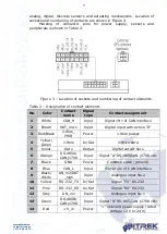
analog, digital, discrete sensors and actuating mechanisms. Location of
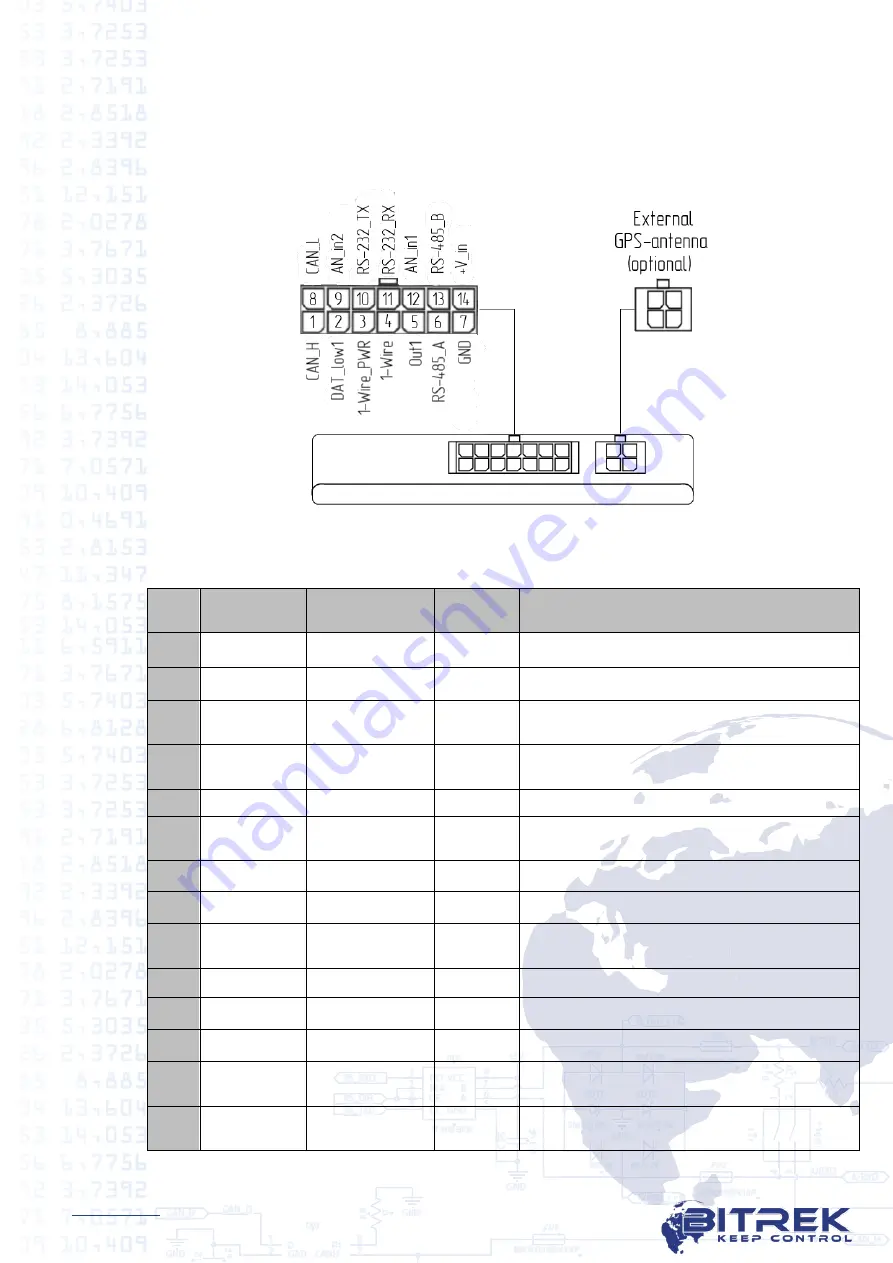
sockets and numbering of contacts are shown in Figure 3.
Marking of connector pins for power supply, sensors and
peripherals is shown in Table 2.
Figure 3 – Location of sockets and numbering of contact elements.
Table 2 – Designation of contact elements
No.
Color
Contact
name
Signal
type
Contact assignment
1
White
CAN_H
Input
Signal «H» of CAN interface
2
Brown
DAT_low 1
Input
Digital input with active "0"
3
Red/Black
1-Wire_
PWR
Power
1-Wire power
4
Yellow/
Green
1-Wire
In/Out
1-Wire data
5
Violet
Out 1
Output
Digital output No.1
6
Orange
RS-485A/
CAN j1708
Input
Signal "A" RS-485/CAN j1708 «A»
7
Black
GND
Power
Common cable (ground)
8
Blue
CAN_L
Input
Signal «L» of CAN interface
9
Black/
White
AN_in2/DAT
_high
Input
Analogue input No.2
10
Yellow
RS-232_TX In/Out
Signal “TX” RS-232
11
Pink
RS-232_RX In/Out
Signal “RX” RS-232
12
Grey
AN_in1
Input
Analogue input No.1
13
Green
RS-485B/
CAN j1708
Input
Signal "B" RS-485/CAN j1708 «B»
14
Red
+V_in
Power
"+" onboard power supply (rated
voltage 12 V or 24 V)


