


5
www.bindicator.com
VRF180913 Rev. A
5
IV. MECHANICAL INSTALLATION
WARNING: REMOVE POWER FROM THE UNIT BEFORE INSTALLING, REMOVING, OR MAKING
ADJUSTMENTS.
GUIDELINES
The following precautions should be observed when installing and operating the VRF II Series units:
• The installation and wiring of this product must comply with all national, federal, state, municipal and
local codes that apply.
• The VRF II Series is a precision device - handle it carefully to prevent damage to the probe.
• Do not allow moisture to enter the electronics enclosure. Conduit should slope downward from the
VRF II Series housing. Install drip loops (or drain fitting) and seal conduit with silicone rubber product.
CAUTION: ATTEMPTING TO TIGHTEN VRF II SERIES UNITS BY ROTATING THE HOUSING OR PROBE
MAY DAMAGE THE UNIT AND VOID THE WARRANTY.
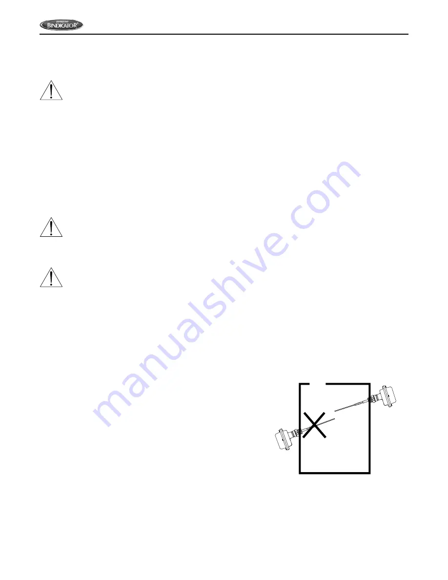
CAUTION: WHETHER MOUNTING DIRECTLY THROUGH A SIDE WALL, OR PIPE EXTENDED AND
MOUNTED VERTICALLY THOUGH THE TOP OF A VESSEL, NEVER ATTEMPT TO MOUNT THROUGH A
FULL COUPLING.
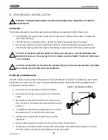
MOUNTING CONSIDERATIONS
The VRF II Series must be located at the position where level indication is desired. The probes may be mounted
through the top or side wall of the vessel. To ensure reliable operation, observe the following guidelines when
choosing the mounting location.
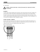
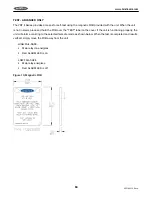
Figure 1. Mounting Orientation
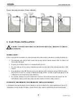
• Do not mount the probe directly in the flow of material.
• Do not mount the probe in an area where it can contact the
vessel.
• Mount probe so that the Pro-Guard
®
section of the probe is
fully in the tank or chute where level of product will come and
go from it.
• In installations where there are multiple probes, do not mount
the probes within 12 inches (30.5 cm) of each other.
• If probes will be tip extended, contact factory for further
instructions.
• Remote cable, between probe and electronics, cannot exceed 100 feet (30.5 m).
• If necessary, use a baffle to protect the probe from falling material. The baffle should be placed 6 to 8 inches
(15 to 20 cm) above the probe so that material will not become packed.
Содержание VRF II Series
Страница 1: ...IOMVRF180713 Rev A VRF II Series Installation Operation Manual IOMVRF180913 Rev A ...
Страница 2: ......
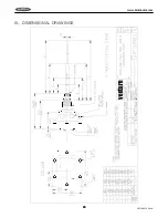
Страница 24: ...20 VRF180913 Rev A www bindicator com 20 IX DIMENSIONAL DRAWINGS venture ...
Страница 25: ...21 www bindicator com VRF180913 Rev A 21 ...
Страница 26: ...22 VRF180913 Rev A www bindicator com 22 venture ...
Страница 27: ...23 www bindicator com VRF180913 Rev A 23 ...
Страница 28: ...24 VRF180913 Rev A www bindicator com 24 Optional Lights venture ...
Страница 29: ...25 www bindicator com VRF180913 Rev A 25 Optional Lights ...
Страница 30: ...26 VRF180913 Rev A www bindicator com 26 Notes ...
Страница 31: ...27 www bindicator com VRF180913 Rev A 27 Notes ...


