

13
www.bindicator.com
VRF180913 Rev. A
13
VI. SET-UP
WARNING: REMOVE POWER FROM THE UNIT BEFORE INSTALLING, REMOVING OR MAKING
ADJUSTMENTS.
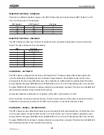
OPERATION
The VRF II Series will begin operating and the green Power LED will be illuminated when power is applied. Once
properly installed, the VRF II Series should be calibrated (refer to Calibration Section) when material is below
the probe. The status of the red Alarm LED is determined by the selected fail-safe mode and whether or not the
probe is in material. Refer to Fail-Safe Operation section. If the unit is calibrated prior to its final installation or if it
is moved from one installation to another, recalibration is required.
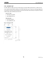
PRODUCT OVERVIEW - STANDARD
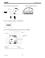
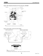
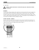
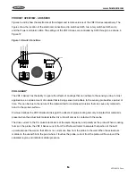
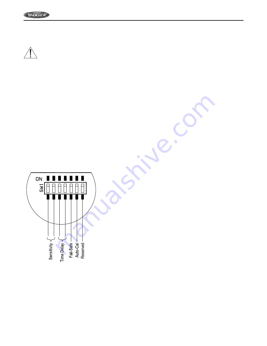
Figures 3 and 8 show the electronics of the integral and remote versions of the VRF II Series respectively. The
figures show the location of the electrical connections, dip switches SW1, and the Power and Alarm LEDs. The
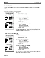
settings of the VRF II Series are controlled by SW1 as shown in Figure 11.
Figure 11: Switch Functions
Содержание VRF II Series
Страница 1: ...IOMVRF180713 Rev A VRF II Series Installation Operation Manual IOMVRF180913 Rev A ...
Страница 2: ......
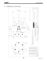
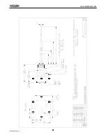
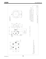
Страница 24: ...20 VRF180913 Rev A www bindicator com 20 IX DIMENSIONAL DRAWINGS venture ...
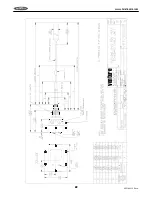
Страница 25: ...21 www bindicator com VRF180913 Rev A 21 ...
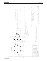
Страница 26: ...22 VRF180913 Rev A www bindicator com 22 venture ...
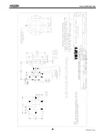
Страница 27: ...23 www bindicator com VRF180913 Rev A 23 ...
Страница 28: ...24 VRF180913 Rev A www bindicator com 24 Optional Lights venture ...
Страница 29: ...25 www bindicator com VRF180913 Rev A 25 Optional Lights ...
Страница 30: ...26 VRF180913 Rev A www bindicator com 26 Notes ...
Страница 31: ...27 www bindicator com VRF180913 Rev A 27 Notes ...


