Fig. 12
Fig. 13
Fig. 15
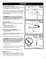
(Fig. 11-12)
ADJUSTING TABLE BEVEL
(Fig. 12)
ADJUSTING DEPTH GAUGE
(Fig. 13-15)
CHANGING SPEEDS
Drive belt
Motor pulley
Pivot nut
Pivot bolt
Tension bolt
Motor
Depth stop
locking collar
Depth gauge
14
ASSEMBLY & ADJUSTMENTS
3. Rotate the table adjustment handle counterclockwise to
lower the table.
4. Position the table to the desired height and retighten the
table lock handle.
The drill press is equipped with a tilting table that allows
you to drill angled holes. The table can be tilted left or right,
from 0º to 45º.
To tilt the table:
1. Loosen the large hex bolt located underneath the table.
2. Use the bevel scale to tilt the table to the desired angle.
3. Retighten the hex bolt securely.
Adjust the depth gauge when you need to drill a number of
holes to exactly the same depth.
1. Loosen the depth stop locking collar.
2. Rotate depth gauge to desired setting.
3. Retighten depth stop locking collar, if needed.
The spindle speed is determined by the location of the belt
on the pulleys inside the head assembly. The speed chart
located on the cover inside the head assembly shows the
recommended speed and pulley configuration for each
drilling operation.
NOTE
: The pivot bolts located on the side of the tool should
allow the motor to move freely once the tension bolt is
loosened.If the motor is difficult to move, it may be necessary
to loosen the pivot bolts slightly (1/4 turn). Do not retighten.
1. Lift head assembly cover from side to open.
2. Loosen the tension bolt until there is enough slack in the
belt for it to be repositioned around the pulleys.
3. Reposition the belt according to the speed chart.
Fig. 14
Spindle pulley
Содержание 10-INCH
Страница 23: ...EXPLODED VIEW PARTS LIST...


