Big Joe CB33 Скачать руководство пользователя страница 96

12-18

BL-CB33-0115 - 03-01-2018

Figure 12-8 Gear Case Assembly - Used between serial # S2410420 and 326140869

DP_0029

Содержание CB33

Страница 1: ...bigjoeforklifts com CB33 SELF PROPELLED POWER STEERING COUNTERBALANCED LIFT TRUCK Operation Maintenance Repair Parts List NOTE For the most current parts information and service updates please refer t...

Страница 2: ...l care when operating on ramps travel slowly and do not angle or turn Travel with load downhill Do not overload truck Check nameplate for capacity and load center information When using forks space fo...

Страница 3: ...5 2 1 GAS RETURN SPRING REPLACEMENT 5 3 5 2 2 CONTROL ARM REMOVAL 5 4 5 2 3 CONTROL ARM INSTALLATION 5 4 5 3 COMPARTMENT COVERS 5 4 5 3 1 REMOVAL 5 4 5 3 2 INSTALLATION 5 4 5 4 STEERING CONTROL 5 4 5...

Страница 4: ...E MAST 9 10 9 9 TILT CYLINDER MOUNTING 9 11 9 10 TILT CYLINDER 9 13 10 1 ELECTRICAL SYSTEM 10 2 10 2 ELECTRICAL PANEL 10 3 10 3 TRANSMISSION MOTOR BRAKE ASSEMBLY 10 5 12 1 CONTROL ARM 12 2 12 2 CONTRO...

Страница 5: ...URES The CB33 is designed and engineered to provide max imum safety for operator and payload Some of the safety features incorporated into the design are Dead man brake to apply the brake and cut off...

Страница 6: ...B33 Lift Truck R7242 ITEM COMPONENT 1 Chassis 2 Drive wheel 3 Battery Discharge Indicator 4 Key Switch 5 Control Handle 6 Battery Disconnect 7 Controller 8 Mast 9 Back Rest 10 Forks 11 Load Wheel 12 H...

Страница 7: ...by a qualified person on a regular basis Do not exceed the rated capacity Overloading may result in damage to the hydraulic system and struc tural components Be certain that the lifting mechanism is...

Страница 8: ...as been restored to a safe operating condition Do not make any unauthorized repairs or adjustments All service must be performed by a qualified maintenance technician Table 2 1 Operator Checks ITEM PR...

Страница 9: ...BL CB33 0115 03 01 2018 2 3 Figure 2 2 Sample of Operator Check List R6479...

Страница 10: ...Control Head 2 5 DRIVING AND STOPPING PROCEDURES 1 Connect the batteries and turn on the key switch Grasp the grips of the steering head so that the speed control can be comfortably operated by either...

Страница 11: ...rol arm to the upright position when the control arm is released If the control arm does not return fully the control arm gas spring requires replacement Return truck to maintenance for repair 2 7 LOA...

Страница 12: ...2 6 BL CB33 0115 03 01 2018 NOTES...

Страница 13: ...affected A baking soda solution one pound to one gallon of water applied to spilled acid until bub bling stops neutralizes the acid for safe handing and disposal Leakage voltage from battery terminal...

Страница 14: ...formed during charging is highly explosive and can cause seri ous injury 1 Charge the battery only in areas designated for that use 2 Make certain the charger being used matches the voltage and amper...

Страница 15: ...being a valve regulated battery it never requires watering 3 4 CHARGING BATTERIES Charging requirements will vary depending on depth of discharge and temperature Follow safety rules when placing a ba...

Страница 16: ...ng freely With lift carriage fully lowered spray or brush on a film of SAE 30 or 40 engine oil Table 3 2 Recommended Lubricants See Table 3 3 for Application No 1 Transmission oil EP SAE 80W 90 Transm...

Страница 17: ...r Mast Brush No 2 Full length of channel where rollers operate 2 Lift Chain Brush or Spray No 4 See Paragraph 3 6 3 Lift Carriage Brush No 2 Light coating where forks slide 4 Hydraulic Reservoir Capac...

Страница 18: ...3 6 BL CB33 0115 03 01 2018 NOTES...

Страница 19: ...rd or reverse All other functions operate normally a Check all wiring A loose con nection may be the cause of malfunction Tighten all loose connections before further troubleshooting b Defective deadm...

Страница 20: ...orks do not lift to top a Oil level too low Add oil to reservoir b Load larger than capacity Refer to I D plate for capacity Weak slow or uneven action of hydraulic system a Defective pump or relief v...

Страница 21: ...for leaking fitting in hydrau lic line and repair as required Repack lift cylinder or replace or pump motor assembly Truck moves forward when arm is pulled down a Belly button switch defective Check...

Страница 22: ...vert temperature when the latest event of every alarm occurred This function permits a deeper diagnosis of problems as the recent history can be revisited 4 1 3 2 Logbook Access To view the alarm logb...

Страница 23: ...ss the ROLL down button or the ROLL up but ton to find the ADJUSTMENTS display 4 Press the ENTER button to view the adjustments 5 Press the ROLL down button or the ROLL up but ton to find the adjustme...

Страница 24: ...active at key on Presence man sensor was active at key on Check the wiring Check the micro switches It could also be an error sequence made by the operator A failure in the logic is possi ble too so w...

Страница 25: ...larm occurs permanently it is necessary to replace the controller If the alarm disap pears the previously stored parameters will have been replaced by the default parame ters with the temperature incr...

Страница 26: ...higher than 2Vdc to detect the condition of a bro ken sense diode Check the Voltage on NPOT and the potenti ometer connections 51 TILLER OPEN Warning When the tiller is released after a fixed period...

Страница 27: ...Check if there is a short or a low impedance between the negative of this coil and BAT This warning also occurs if the external load is not present and the parameter EV2 in the Set Options menu is se...

Страница 28: ...rs when both fork movement requests Lift Lower are active at the same time Check the wiring of the lift and lower inputs use the readings in the TEST to facilitate the troubleshooting Check the micros...

Страница 29: ...m the main uC through this serial interface It is necessary to replace the controller 13 EEPROM KO It occurs if a test to write and read one location in EEPROM fails The SW expects to read the written...

Страница 30: ...reason for keeping the main contactor open 53 STBY I HIGH This alarm occurs two ways 1 In the initial rest state after key on if the outputs of the current amplifiers are not comprised in the window 2...

Страница 31: ...the bat tery positive arrives to the controller Check the continuity of the wire in the phase U of the motor Otherwise it is necessary to replace the controller 73 POWER FAILURE 1 This alarm occurs w...

Страница 32: ...o a plus battery or to a minus battery In the first case safety contacts connected to a plus battery when the safety contacts are open CNA 4 is connected to a minus bat tery through a load Only a harn...

Страница 33: ...to off this alarm occurs if the feedback encoder counting does not change its value even if commanded to change In application with the feedback potentiome ter verify potentiometer is not mechanically...

Страница 34: ...l interface It is necessary to replace the controller 237 WAITING DATA This warning occurs only if CAN BUS is PRESENT At key on the EPS AC0 asks the traction controller to send a list of parameters vi...

Страница 35: ...esolution or a wrong connection between the two encoder channels In this latest case exchange the connections 242 Q LINE SENSOR KO This alarm occurs when the mean voltage of the Quadrature line of the...

Страница 36: ...ror not matched with the one that the slave uC is detecting Furthermore this alarm occurs if the main uC is detecting no steering limitation meanwhile the slave uC is detecting a steering limitation I...

Страница 37: ...closed It is necessary to replace the controller 252 KS OPEN This alarm occurs if the slave uC detects the safety contact of the main uC open when expected being closed It is necessary to replace the...

Страница 38: ...4 20 BL CB33 0115 03 01 2018 NOTES...

Страница 39: ...5 1 CONTROL HEAD 5 1 1 Cap Assembly Removal 1 Turn off the key switch and disconnect the batter ies 2 Remove screws As cap is removed cover and spring can be removed 3 Lift up cap tag and disconnect h...

Страница 40: ...ly Installation 1 Hold cap in place and reconnect harness to har nesses in control handle 2 As cap is installed install cover and spring Secure cap with screws 3 Reconnect the batteries and turn on th...

Страница 41: ...as described in para graph 5 1 2 5 1 7 Horn Switch Replacement 1 Remove the cap assembly as described in para graph 5 1 1 2 Remove two screws two mounts and horn button 3 Remove switch from cap 4 Pos...

Страница 42: ...on hinges Close the covers and secure with two screws and washers 6 Reconnect the batteries and turn on the key switch 5 4 STEERING CONTROL 5 4 1 Removal 1 Turn off the key switch and disconnect the b...

Страница 43: ...osition steering motor on the frame and secure with four screws 2 Install gear on steering motor and secure with screw lock washer and washer 3 Reconnect harness to steering motor 4 Install position s...

Страница 44: ...5 6 BL CB33 0115 03 01 2018 NOTES...

Страница 45: ...2 Turn off the key switch and disconnect the batter ies 3 Remove the compartment covers as described in paragraph 5 3 4 Disconnect electric brake from the harness 5 Remove three screws and remove bra...

Страница 46: ...6 2 BL CB33 0115 03 01 2018 Figure 6 1 Drive Assembly DP_0004...

Страница 47: ...screws bearing and gear from transmission 7 Install new transmission by reversing the steps above 7 3 Load Wheel 7 3 1 Removal 1 Turn off the key switch and disconnect the batter ies 2 Block the driv...

Страница 48: ...7 2 BL CB33 0115 03 01 2018 Figure 7 1 Drive Assembly DP_0004...

Страница 49: ...BL CB33 0115 03 01 2018 7 3 Figure 7 2 Load Wheels DP_0007...

Страница 50: ...7 4 BL CB33 0115 03 01 2018 NOTES...

Страница 51: ...ts on outer mast to allow for adjustment of middle jam nuts 4 Break the lower jam nuts located below the mounts on outer mast free from the middle jam nuts 5 Take up slack in both lift chains with mid...

Страница 52: ...8 2 BL CB33 0115 03 01 2018 Figure 8 2 Elevation System Telescopic DP_0008...

Страница 53: ...Loosen jam nuts the mount of outer mast to allow for adjustment of middle jam nut 4 Break the lower jam nuts located below the mount of outer mast free from the middle jam nuts 5 Take up slack in bot...

Страница 54: ...8 4 BL CB33 0115 03 01 2018 Figure 8 3 Mast Three Stage Mast DP_0009...

Страница 55: ...make certain power is disconnected 4 Remove cotter pin and clevis pin connecting chain to chain anchor at the lift carriage 5 Remove cotter pin and clevis pin connecting chain to chain anchor at free...

Страница 56: ...8 6 BL CB33 0115 03 01 2018 NOTES...

Страница 57: ...s are raised pressure exists in the hydraulic system lines and fittings To ensure release of pressure forks must be fully lowered and the batteries discon nected before performing any mainte nance on...

Страница 58: ...9 2 BL CB33 0115 03 01 2018 Figure 9 1 Hydraulic System DP_0018...

Страница 59: ...other lift truck or suitable jack raise mast far enough to remove pressure on the lift cylinder CAUTION Hydraulic oil can damage parts Wipe off any oil immediately Provide a container under the line o...

Страница 60: ...9 4 BL CB33 0115 03 01 2018 Figure 9 3 Elevation System Telescopic DP_0008...

Страница 61: ...der tube 9 3 3 Installation 1 Using another lift truck or suitable jack raise mast far enough to allow installation of the lift cylinder 2 Slowly lower mast while aligning cylinder with the tap on mas...

Страница 62: ...ent make certain power is disconnected 3 Using another lift truck or suitable jack raise lift carriage far enough to remove pressure on the free lift cylinder 4 Remove cotter pin and clevis pin connec...

Страница 63: ...under the line or fitting before discon necting 6 Remove chains from sheaves 7 Disconnect the tube from the bottom of lift cylin der 8 Support cylinder and remove two screws two lock washers and two f...

Страница 64: ...tion 1 Position cylinder on inner mast and secure with two screws two lock washers and two flat wash ers 2 Reconnect the tube to the bottom of the cylinder 3 Position ram head and bracket and on cylin...

Страница 65: ...gland nut 3 Remove wiper and O ring from gland nut 4 Pull out piston rod 5 Remove collar and piston from piston rod 6 Remove backup ring and packing from piston rod 7 Coat all parts with hydraulic oil...

Страница 66: ...9 10 BL CB33 0115 03 01 2018 Figure 9 8 Secondary Lift Cylinder Three Stage Mast DP_0012...

Страница 67: ...cted CAUTION Hydraulic oil can damage parts Wipe off any oil immediately Provide a container under the line or fitting before discon necting 3 Remove the front compartment covers as described in parag...

Страница 68: ...stall dust seal seal and O ring in gland nut 14 Install gland nut in tube 15 Install bearing and retaining rings in clevis 16 Install clevis on piston rod and secure with bolt lock washer and nut 9 5...

Страница 69: ...BL CB33 0115 03 01 2018 9 13 Figure 9 10 Tilt Cylinder DP_0016...

Страница 70: ...9 14 BL CB33 0115 03 01 2018 NOTES...

Страница 71: ...e the connections to the buss bars are tight Use two well insulated wrenches for this task in order to avoid bending the buss bars 10 1 3 Panel Removal 1 Turn off the key switch and disconnect the bat...

Страница 72: ...10 2 BL CB33 0115 03 01 2018 Figure 10 1 Electrical System R6478 DP_0022...

Страница 73: ...BL CB33 0115 03 01 2018 10 3 Figure 10 2 Electrical Panel R6478 DP_0023...

Страница 74: ...stall drive motor onto bearing 2 Remove six screws six lock washers and six flat washers to secure the motor to the bearing 3 Position cables as noted in removal and recon nect cables to the drive mot...

Страница 75: ...BL CB33 0115 03 01 2018 10 5 Figure 10 3 Transmission Motor Brake Assembly DP_0004...

Страница 76: ...10 6 BL CB33 0115 03 01 2018 NOTES...

Страница 77: ...BL CB33 0115 03 01 2018 11 1 SECTION 11 OPTIONAL EQUIPMENT...

Страница 78: ...11 2 BL CB33 0115 03 01 2018 NOTES...

Страница 79: ...BL CB33 0115 03 01 2018 12 1 SECTION 12 ILLUSTRATED PARTS BREAKDOWN Following is an illustrated parts breakdown of assemblies and parts associated with the CB33 Lift Truck...

Страница 80: ...12 2 BL CB33 0115 03 01 2018 Figure 12 1 Steering System DP_0001...

Страница 81: ...10 2333 340000 01 B CONTROL HEAD 1 Used when Side Shift 10a 2333 340000 00 B CONTROL HEAD 1 Standard 11 0000 000114 00 NUT M53 X 1 5 1 12 0000 000143 00 WASHER LOCK M52 1 13 0000 000681 00 KEY C8 X 7...

Страница 82: ...12 4 BL CB33 0115 03 01 2018 Figure 12 1 Steering System Continued DP_0001...

Страница 83: ...000321 00 SCREW M8 X 20 7 30 2322 300001 00 SUPPORT 1 31 0000 000109 00 SCREW M8 X 16 3 32 1221 300002 00 MOUNTING PLATE 1 33 1221 520007 0A POTENTIOMETER WITH WIRE HARNESS 1 34 2333 520002 10 WIRE H...

Страница 84: ...12 6 BL CB33 0115 03 01 2018 Figure 12 2 Control Head DPP_0002...

Страница 85: ...UTTON SWITCH HARNESS 1 11 2333 520003 10 POTENTIOMETER 1 12 2333 520006 10 TILT SWITCH HARNESS 1 13 2333 340017 00 SCREW ST2 9 X 9 5 2 14 2333 340009 00 MOUNT SEAT 2 15 2333 340012 00 SCREW ST2 9 X 13...

Страница 86: ...12 8 BL CB33 0115 03 01 2018 Figure 12 3 Control Head when Side Shift option DP_0035...

Страница 87: ...WITCH HARNESS 1 11 2333 520003 10 POTENTIOMETER 1 12 2333 520006 10 TILT SWITCH HARNESS 1 13 2333 340017 00 SCREW ST2 9 X 9 5 2 14 2333 340009 00 MOUNT SEAT 2 15 2333 340012 00 SCREW ST2 9 X 13 2 16 2...

Страница 88: ...12 10 BL CB33 0115 03 01 2018 Figure 12 4 Drive System DP_0003...

Страница 89: ...E ASSEMBLY 1 Used up to serial S2410419 1a 2333 200000 1A DRIVE ASSEMBLY 1 Used between serial S2410420 and 325130600 1b 2333 200000 1B DRIVE ASSEMBLY 1 Used between serial 325130601 and 326140869 1c...

Страница 90: ...12 12 BL CB33 0115 03 01 2018 Figure 12 5 Drive Assembly Used up to serial S2410419 DP_0004...

Страница 91: ...M8 X 40 12 8 0000 000154 00 SCREW M8 X 35 6 9 0000 000159 00 WASHER LOCK M8 6 10 0000 000176 00 WASHER FLAT M8 6 11 0000 000516 00 SCREW M12 X 40 6 12 0000 000060 00 WASHER LOCK M12 6 13 0000 000373...

Страница 92: ...12 14 BL CB33 0115 03 01 2018 Figure 12 6 Drive Assembly Used between serial S2410420 and 325130600 DP_0028...

Страница 93: ...6 6 1280 520009 10 SWITCH WIRE HARNESSII 1 7 0000 000006 00 SCREW M6 30 1 8 1280 210053 10 ELASTIC COLLAR 1 9 0000 000322 00 SCREW M8 25 3 10 0000 000159 00 LOCKWASHER 8 7 11 CK10 240000 20 STEERING...

Страница 94: ...12 16 BL CB33 0115 03 01 2018 Figure 12 7 Drive Assembly Used from serial 325130601 DP_0032...

Страница 95: ...0000 000322 00 SCREW M8 25 3 10 0000 000159 00 LOCKWASHER 8 7 11 CK10 240000 20 STEERING MOTOR 1 12 1280 210042 10 MOTOR GEAR 1 13 2415 220000 1A GEAR CASE ASSEMBLY 1 Used between serial 325130601 and...

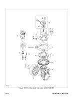
Страница 96: ...12 18 BL CB33 0115 03 01 2018 Figure 12 8 Gear Case Assembly Used between serial S2410420 and 326140869 DP_0029...

Страница 97: ...5 0000 000055 00 SCREW M6 16 8 6 2415 GB10 00 SPIRAL BEVEL GEAR KIT 1 Includes 2 gears 7 1120 240007 30 WASHER 1 8 1120 240008 30 LOCKING PLATE 1 9 0000 000277 00 BOLT M8 25 3 10 0000 001054 00 BEARIN...

Страница 98: ...12 20 BL CB33 0115 03 01 2018 Figure 12 8 Gear Case Assembly Used between serial S2410420 and 326140869 Continued DP_0029...

Страница 99: ...BOLT M8 20 6 24 0000 001699 00 SNAP RING 55 1 25 2415 220015 10 SEAL WASHER 1 26 0000 000762 00 ELASTIC COLLAR 62 1 27 0000 000183 00 RETAINER RING 35 1 28 0000 001282 10 BEARING 2 29 2415 220011 10 S...

Страница 100: ...12 22 BL CB33 0115 03 01 2018 Figure 12 9 Gear Case Assembly Used from serial 326140870 DP_0042...

Страница 101: ...WASHER TC35 62 7 1 9 0000 001445 00 BEARING 2 10 ZK18 240010 00 SLEEVE 1 11 ZK18 GBA0 00 GEAR KIT Z1 Z2 28 94 1 The kit includes 2 gears Pos 11 12 ZK18 240006 00 COVER PLATE 1 13 0000 000762 00 ELASTI...

Страница 102: ...12 24 BL CB33 0115 03 01 2018 Figure 12 9 Gear Case Assembly Used from serial 326140870 Continued DP_0042...

Страница 103: ...0 10 GEAR KIT Z1 Z2 6 43 1 27 ZK18 240007 00 OUTPUT SHAFT 1 28 0000 001790 00 BEARING 2 29 0000 001791 00 ELASTIC COLLAR 140 1 30 0000 001792 00 RETAINER RING 100 1 31 0000 001787 00 SEAL WASHERTC140...

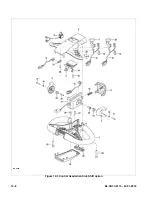
Страница 104: ...12 26 BL CB33 0115 03 01 2018 Figure 12 10 Compartment DP_0005...

Страница 105: ...1000 00 COVER ASSEMBLY L 1 8 2333 141000 00 COVER ASSEMBLY R 1 Used up to serial num ber 326110893 8a 2333 141000 0A COVER ASSEMBLY R 1 Used from serial num ber 326110894 9 1220 150005 00 NUT M8 2 10...

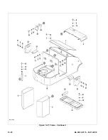
Страница 106: ...12 28 BL CB33 0115 03 01 2018 Figure 12 11 Frame DP_0006...

Страница 107: ...0176 00 WASHER FLAT M8 10 11 0000 000026 00 SCREW M8 X 30 2 12 0000 000015 00 SCREW M6 X 10 1 13 0000 000056 00 WASHER LOCK M6 1 14 0000 000380 00 WASHER FLAT M6 1 15 0000 000087 00 SCREW M12 X 25 4 1...

Страница 108: ...12 30 BL CB33 0115 03 01 2018 Figure 12 11 Frame Continued DP_0006...

Страница 109: ...0115 03 01 2018 12 31 FRAME CONTINUED Pos Part Number Description Qty Reqd Notes 23 1280 180001 0A BLOCK 1 24 0000 000279 00 BOLT M8 X 35 1 25 2125 100002 00 BATTERY CLIP 1 26 2140 100001 00 BATTERY...

Страница 110: ...12 32 BL CB33 0115 03 01 2018 Figure 12 12 Load Wheels DP_0007...

Страница 111: ...20 00 BOLT M6 X 16 2 4 0000 000056 00 WASHER LOCK M6 2 5 0000 000380 00 WASHER FLAT M6 2 6 2320 600002 00 RETAINER 1 7 2320 601100 00 LOAD WHEEL 1 8 2320 600001 00 MOUNTING BASE 1 9 0000 000379 00 WAS...

Страница 112: ...12 34 BL CB33 0115 03 01 2018 Figure 12 13 Elevation System Telescopic DP_0008...

Страница 113: ...0 WASHER LOCK M12 2 10 0000 000283 00 BOLT M10 X 35 4 11 0000 000063 00 WASHER LOCK M10 6 12 2214 600005 00 SHIM A R As Required 13 2214 600004 0A CYLINDER BRACKET 2 14 2214 600003 0A CLINDER CLIP 2 1...

Страница 114: ...12 36 BL CB33 0115 03 01 2018 Figure 12 13 Elevation System Telescopic Continued DP_0008...

Страница 115: ...04 When Side Shift 17de 2333 610000 20 03 OUTER MAST 1 Used for Lift Height 126 When Side Shift 18 LIFT CARRIAGE 2 See Lift Carriage Sec tion 19 2214 600007 00 CUSHION BLOCK II 2 20 2130 500002 0A SEN...

Страница 116: ...12 38 BL CB33 0115 03 01 2018 Figure 12 14 Elevation System Three Stage Mast DP_0009...

Страница 117: ...0 ROLLER ASSEMBLY 8 7 2125 600007 30 BRACKET 1 8 2125 600001 30 ROLLER BRACKET 1 9 2333 420000 30 01 CYLINDER FREE LIFT 1 For Lift Height 157 10 0000 000244 00 BOLT M10 X 30 2 11 LIFT CARRIAGE 2 See L...

Страница 118: ...12 40 BL CB33 0115 03 01 2018 Figure 12 14 Elevation System Three Stage Mast Continued DP_0009...

Страница 119: ...0390 00 WASHER FLAT M5 8 32 2125 500001 3A SENSOR BRACKET 1 Used up to serial number 324170306 32a 2333 500001 30 SENSOR BRACKET 1 Used from serial number 324170307 33 2125 500003 00 PROXIMITY SWITCH...

Страница 120: ...12 42 BL CB33 0115 03 01 2018 Figure 12 14 Elevation System Three Stage Mast Continued ELEVATION SYSTEM THREE STAGE MAST CONTINUED DP_0009...

Страница 121: ...18 12 43 Pos Part Number Description Qty Reqd Notes 47 2333 500001 50 Board 1 Optional 48 CK10 520015 10 Warning Light 1 49 2333 520007 50 Warning Light Wiring 1 50 0000 000139 00 Nut M4 2 51 0000 000...

Страница 122: ...12 44 BL CB33 0115 03 01 2018 Figure 12 15 Lift Carriage Telescopic LIFT CARRIAGE TELESCOPIC DP_0013...

Страница 123: ...3 0000 000373 00 WASHER FLAT M12 4 4 2320 631000 00 BACKREST 1 5 2130 631000 00 LIFT CARRIAGE 1 5a 2130 631000 10 LIFT CARRIAGE 1 When Side Shift option 6 2125 630001 00 FORK 2 7 2125 630001 10 PIN AS...

Страница 124: ...12 46 BL CB33 0115 03 01 2018 Figure 12 16 Lift Carriage Three Stage Mast DP_0014...

Страница 125: ...0419 6 2125 630001 00 FORK 2 6a 2333 630001 50 FORK 2 When Side Shift option 7 2125 630001 10 PIN ASSEMBLY 2 8 2125 612000 00 ROLLER ASSEMBLY 4 9 0000 000030 00 SCREW M10 X 16 1 10 2125 642000 30 PLAT...

Страница 126: ...12 48 BL CB33 0115 03 01 2018 Figure 12 17 Side Shift Assembly DP_0034...

Страница 127: ...ARRIAGE 1 3 2130 641002 40 SIDE SHIFT PLATE 1 4 0000 000587 00 LUBRICATION FITTING M6 4 5 2130 641003 40 SIDE SHIFT PLATE UPPER 2 6 0000 001425 00 ROLL PIN M5 X 40 2 7 2130 641004 40 LOCKING BLOCK 2 8...

Страница 128: ...12 50 BL CB33 0115 03 01 2018 Figure 12 18 Chain Assembly DP_0017...

Страница 129: ...TO FREE LIFT CYL 1 Used for Lift Height 104 Telescopic Mast 5a 2125 640000 00 04 CHAIN I MOUNTS TO FREE LIFT CYL 1 Used for Lift Height 126 Telescopic Mast 5b 2125 651000 30 01 CHAIN I MOUNTS TO FREE...

Страница 130: ...12 52 BL CB33 0115 03 01 2018 Figure 12 19 Hydraulic System Used up to serial number 324190319 not with Side Shift DP_0018...

Страница 131: ...0 WASHER LOCK M6 4 8 0000 000620 00 BOLT M6 X 16 4 9 2125 420001 00 MAGNET 1 10 0000 000635 00 PLUG M18 X 1 5 1 11 0000 000510 00 WASHER M20 1 12 2130 423000 00 FILTER 1 13 2333 420000 00 HOSE 2 14 23...

Страница 132: ...12 54 BL CB33 0115 03 01 2018 Figure 12 20 Hydraulic System Used from serial number 324190320 Not with Side Shift DP_0031...

Страница 133: ...m ber 326120516 6 2333 411000 00 TANK 1 7 0000 000056 00 LOCKWASHER 6 4 8 0000 000620 00 BOLT M6 16 4 9 2125 420001 00 MAGNET 1 10 0000 000635 00 PLUG M18 1 5 1 11 0000 000510 00 WASHER 20 3 12 2130 4...

Страница 134: ...12 56 BL CB33 0115 03 01 2018 Figure 12 21 Hydraulic System Used with Side Shift DP_0036...

Страница 135: ...1000 00 TANK 1 7 0000 000056 00 LOCKWASHER 6 4 8 0000 000620 00 BOLT M6 16 4 9 2125 420001 00 MAGNET 1 10 0000 000635 00 PLUG M18 1 5 1 11 0000 000510 00 WASHER 20 3 12 2130 423000 00 FILTER 1 13 2333...

Страница 136: ...12 58 BL CB33 0115 03 01 2018 Figure 12 22 Tilt System DP_0015...

Страница 137: ...OLT M8 X 20 2 2 0000 000159 00 WASHER LOCK M8 4 3 0000 000176 00 WASHER FLAT M8 4 4 2333 400001 00 SHAFT 2 5 2333 440000 00 TILT CYLINDER 2 Used up to Serial Num ber 324170306 5a 2333 440000 0A TILT C...

Страница 138: ...12 60 BL CB33 0115 03 01 2018 Figure 12 23 Lift System Telescopic Not with Side Shift DP_0019...

Страница 139: ...LD 1 Used up to serial num ber 324190319 4a 2333 430001 30 MANIFOLD 1 Used from serial num ber 324190320 5 2712 141300 00 PLUG G1 4 1 Used up to serial num ber 324190319 5a 2712 201300 00 PLUG M20 X 1...

Страница 140: ...12 62 BL CB33 0115 03 01 2018 Figure 12 24 Lift System Telescopic With Side Shift DP_0037...

Страница 141: ...0 000169 00 Screw M8 30 2 7 2701 161600 00 Connector M16 1 5 M16 1 5 2 8 0000 000510 00 Washer 20 1 9 0000 000044 00 Washer 14 4 10 3218 724000 00 Metal Tube 1 11 2333 432000 20 01 Oil Pipe 1 Used wit...

Страница 142: ...12 64 BL CB33 0115 03 01 2018 Figure 12 25 Lift System Three Stage Mast Not with Side Shift DP_0020...

Страница 143: ...0 CONNECTOR M20 1 5 M20 1 5 1 Used from serial number 324190320 8 0000 000044 00 SEAL M14 1 Used up to serial number 324190319 8a 0000 000510 00 SEAL M20 1 Used from serial number 324190320 9 2125 430...

Страница 144: ...12 66 BL CB33 0115 03 01 2018 Figure 12 25 Lift System Three Stage Mast with Side Shift DP_0038...

Страница 145: ...5 M20 1 5 1 8 0000 000510 00 WASHER 20 1 9 2333 431000 30 METALLIC OIL PIPE ASSEMBLY 1 10 2333 432000 30 METALLIC OIL PIPE ASSEMBLY 1 11 2706 162000 10 CONNECTOR M16 1 5 M20 1 5 1 12 2333 433000 30 0...

Страница 146: ...12 68 BL CB33 0115 03 01 2018 Figure 12 26 Lift Cylinder Telescopic DP_0010...

Страница 147: ...ER 35 X 43 X 5 6 5 1 2 0000 000370 00 O RING 40 X 3 1 1 3 1220 420001 0A GLAND NUT 1 4 2130 410001 00 01 PISTON ROD 1 Used for Lift Height 104 4a 2130 410001 00 02 PISTON ROD 1 Used for Lift Height 12...

Страница 148: ...12 70 BL CB33 0115 03 01 2018 Figure 12 27 Free Lift Cylinder Three Stage Mast DP_0011...

Страница 149: ...1 Includes 1 2 7 1 0000 000045 00 RING WIPER 35 X 43 X 5 6 5 1 2 0000 000690 00 O RING 60 X 3 1 1 3 2130 420002 30 GLAND NUT 1 4 2130 420001 30 01 PISTON ROD 1 Used for Lift Height 157 Three Stage Ma...

Страница 150: ...12 72 BL CB33 0115 03 01 2018 Figure 12 28 Secondary Lift Cylinder Three Stage Mast DP_0012...

Страница 151: ...udes 1 2 3 1 0000 000084 00 RING WIPER 35 X 43 X 5 6 5 1 2 0000 000370 00 O RING 40 X 3 1 1 3 1220 420001 0A GLAND NUT 1 4 2130 410001 30 01 PISTON ROD 1 Used for Lift Height 157 Three Stage Mast 5 21...

Страница 152: ...12 74 BL CB33 0115 03 01 2018 Figure 12 29 Tilt Cylinder Used up to Serial Number 324170306 DP_0016...

Страница 153: ...0 SEAL M47 1 4 0000 001013 00 BOLT M14 X 55 1 5 0000 000233 00 WASHER LOCK M14 1 6 0000 001014 00 NUT M14 1 7 0000 001017 00 DUST SEAL LYO 30 X 47 X 10 1 8 0000 001016 00 SEAL 30 X 43 X 7 1 9 2320 440...

Страница 154: ...12 76 BL CB33 0115 03 01 2018 Figure 12 30 Tilt Cylinder Used from Serial Number 324170307 DP_0033...

Страница 155: ...0 SEAL M47 1 4 0000 001013 00 BOLT M14 X 55 1 5 0000 000233 00 WASHER LOCK M14 1 6 0000 001014 00 NUT M14 1 7 0000 001017 00 DUST SEAL LYO 30 X 47 X 10 1 8 0000 001016 00 SEAL 30 X 43 X 7 1 9 2320 440...

Страница 156: ...12 78 BL CB33 0115 03 01 2018 Figure 12 31 Pump and Motor Not when Side Shift DP_0021...

Страница 157: ...009 0A FILTER STEEL 1 8 2130 470003 40 BRUSH 1 9 0000 000159 00 LOCKWASHER 8 2 10 0000 000110 00 SCREW M8 65 2 11 2130 430012 0A VALVE 12L MIN 1 12 2125 430021 00 WIRE 1 13 2125 430022 00 CLAMP STEEL...

Страница 158: ...12 80 BL CB33 0115 03 01 2018 Figure 12 32 Pump and Motor When Side Shift DP_0039...

Страница 159: ...0000 000159 00 LOCKWASHER 8 2 10 0000 000110 00 SCREW M8 65 2 11 2130 430012 0A VALVE 12L MIN 1 12 2125 430021 00 WIRE 1 13 2125 430022 00 CLAMP STEEL 1 14 2125 430004 00 BUSH 1 15 2125 430005 00 COU...

Страница 160: ...12 82 BL CB33 0115 03 01 2018 Figure 12 33 Electrical System ELECTRICAL SYSTEM DP_0022...

Страница 161: ...Hour meter Set the BDI dial to the fol lowing M Industrial Battery Q Maint Free Battery 7 1220 520007 0D METER WIRING HARNESS 1 8 0000 000170 00 SCREW M6 X 30 2 9 0000 000056 00 WASHER LOCK M6 3 10 2...

Страница 162: ...12 84 BL CB33 0115 03 01 2018 Figure 12 34 Electrical Panel DP_0023...

Страница 163: ...0 000380 00 WASHER FLAT M6 14 5 0000 000196 00 NUT M8 8 6 0000 000210 00 WASHER FLAT M8 4 7 1120 540002 00 FUSE 200A 2 8 0000 000126 00 SCREW M6 X 16 4 9 1280 560002 00 30 CONTROLLER AC 1 10 1120 5400...

Страница 164: ...12 86 BL CB33 0115 03 01 2018 Figure 12 35 Wire Harness Used up to Serial Number S2221337 DP_0024...

Страница 165: ...BL CB33 0115 03 01 2018 12 87 WIRE HARNESS USED UP TO SERIAL NUMBER S2221337 Pos Part Number Description Qty Reqd Notes 1 2333 520001 00 WIRE HARNESS 1 2 1120 500010 00 FUSE 10A 2...

Страница 166: ...12 88 BL CB33 0115 03 01 2018 Figure 12 36 Wire Harness Used from Serial Number S2221338 DP_0040...

Страница 167: ...WIRE HARNESS USED FROM SERIAL NUMBER S2221338 Pos Part Number Description Qty Reqd Notes 1 2333 520001 10 WIRE HARNESS 1 Used from serial S2221338 1a 2333 520001 50 WIRE HARNESS 1 Used when Side Shif...

Страница 168: ...12 90 BL CB33 0115 03 01 2018 Figure 12 37 Wiring Cables DP_0025...

Страница 169: ...00 DRIVE MOTOR CABLE V 1 3 2333 530003 00 DRIVE MOTOR CABLE W 1 4 2333 530004 00 PUMP MOTOR CABLE 1 5 2333 530005 00 PUMP MOTOR CABLE 1 6 2333 530006 10 STREEING MOTOR CABLE U 1 7 2333 530007 10 STREE...

Страница 170: ...Big Lift LLC...

Отзывы: