


BL-CB33-0115 - 03-01-2018
5-3
5-1.3. Control Head Removal.
1.
Remove the cap assembly as described in para-
graph
2.
Tag and disconnect harness from switch and
potentiometer.
3.
Hold control head in place and remove three
screws, lock washers and flat washers. Remove
control head from bracket.
5-1.4. Control Head Installation.
1.
Hold control head in place and secure to bracket
with three screws, lock washers and flat washers .
2.
Reconnect harness to switch and potentiometer.
3.
Install the cap assembly as described in para-
graph
5-1.5. Speed Potentiometer Replacement.
1.
Remove the cap assembly as described in para-
graph
2.
Disconnect harness from potentiometer.
3.
Remove screw, washer and travel control from
potentiometer.
4.
Remove screw, washer and travel control from
other side of potentiometer.
5.
Remove potentiometer from cover.
6.
Position new potentiometer in cover.
7.
Install travel control on potentiometer and secure
with screw, and washer.
8.
Install travel control on the other side of potenti-
ometer and secure with screw, and washer.
9.
Connect harness to potentiometer.
10. Install the cap assembly as described in para-
graph
5-1.6. Belly-Button Switch Replacement.
1.
Remove the cap assembly as described in para-
graph
2.
Disconnect harness from switch.
3.
Remove and replace switch.
4.
Reconnect harness to switch.
5.
Install the cap assembly as described in para-
graph
5-1.7. Horn Switch Replacement.
1.
Remove the cap assembly as described in para-
graph
2.
Remove two screws, two mounts and horn button
.
3.
Remove switch from cap.
4.
Position the new switch in cap.
5.
Position horn button in cap and secure with two
mounts and two screws.
6.
Install the cap assembly as described in para-
graph
5-1.8. Lift and Lower Switch Replacement.
1.
Remove the cap assembly as described in para-
graph
2.
Remove switch assembly from cap.
3.
Install new switch assembly in cap.
4.
Install the cap assembly as described in para-
graph
5-1.9. Tilt Switch Replacement.
1.
Remove the cap assembly as described in para-
graph
2.
Remove two screws and switch assembly form
button.
3.
Secure new switch assembly to button with two
screws.
4.
Install the cap assembly as described in para-
graph
5-2. CONTROL ARM
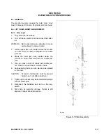
5-2.1. Gas Return Spring Replacement.
The control arm gas return spring is replaced while the
control arm is in the upright position.
1.
Turn off the key switch and disconnect the batter-
ies.
2.
Remove three screws, lock washers, flat washers
and cover.
3.
Secure the control arm in the upright position.
4.
Remove screw and free the gas return spring
from bracket.
5.
Pull downward on the gas return spring to free it
from its seat inside control arm.
6.
Position the new gas return spring inside the con-
trol arm being sure it fully engages its seat.
7.
Position the opposite end of the gas return spring
on bracket and install screw.
8.
Install cover and secure with three screws, lock
washers, flat washers
Содержание CB33
Страница 9: ...BL CB33 0115 03 01 2018 2 3 Figure 2 2 Sample of Operator Check List R6479...
Страница 12: ...2 6 BL CB33 0115 03 01 2018 NOTES...
Страница 18: ...3 6 BL CB33 0115 03 01 2018 NOTES...
Страница 38: ...4 20 BL CB33 0115 03 01 2018 NOTES...
Страница 44: ...5 6 BL CB33 0115 03 01 2018 NOTES...
Страница 46: ...6 2 BL CB33 0115 03 01 2018 Figure 6 1 Drive Assembly DP_0004...
Страница 48: ...7 2 BL CB33 0115 03 01 2018 Figure 7 1 Drive Assembly DP_0004...
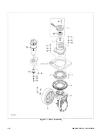
Страница 49: ...BL CB33 0115 03 01 2018 7 3 Figure 7 2 Load Wheels DP_0007...
Страница 50: ...7 4 BL CB33 0115 03 01 2018 NOTES...
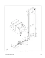
Страница 52: ...8 2 BL CB33 0115 03 01 2018 Figure 8 2 Elevation System Telescopic DP_0008...
Страница 54: ...8 4 BL CB33 0115 03 01 2018 Figure 8 3 Mast Three Stage Mast DP_0009...
Страница 56: ...8 6 BL CB33 0115 03 01 2018 NOTES...
Страница 58: ...9 2 BL CB33 0115 03 01 2018 Figure 9 1 Hydraulic System DP_0018...
Страница 60: ...9 4 BL CB33 0115 03 01 2018 Figure 9 3 Elevation System Telescopic DP_0008...
Страница 66: ...9 10 BL CB33 0115 03 01 2018 Figure 9 8 Secondary Lift Cylinder Three Stage Mast DP_0012...
Страница 69: ...BL CB33 0115 03 01 2018 9 13 Figure 9 10 Tilt Cylinder DP_0016...
Страница 70: ...9 14 BL CB33 0115 03 01 2018 NOTES...
Страница 72: ...10 2 BL CB33 0115 03 01 2018 Figure 10 1 Electrical System R6478 DP_0022...
Страница 73: ...BL CB33 0115 03 01 2018 10 3 Figure 10 2 Electrical Panel R6478 DP_0023...
Страница 75: ...BL CB33 0115 03 01 2018 10 5 Figure 10 3 Transmission Motor Brake Assembly DP_0004...
Страница 76: ...10 6 BL CB33 0115 03 01 2018 NOTES...
Страница 77: ...BL CB33 0115 03 01 2018 11 1 SECTION 11 OPTIONAL EQUIPMENT...
Страница 78: ...11 2 BL CB33 0115 03 01 2018 NOTES...
Страница 80: ...12 2 BL CB33 0115 03 01 2018 Figure 12 1 Steering System DP_0001...
Страница 82: ...12 4 BL CB33 0115 03 01 2018 Figure 12 1 Steering System Continued DP_0001...
Страница 84: ...12 6 BL CB33 0115 03 01 2018 Figure 12 2 Control Head DPP_0002...
Страница 86: ...12 8 BL CB33 0115 03 01 2018 Figure 12 3 Control Head when Side Shift option DP_0035...
Страница 88: ...12 10 BL CB33 0115 03 01 2018 Figure 12 4 Drive System DP_0003...
Страница 90: ...12 12 BL CB33 0115 03 01 2018 Figure 12 5 Drive Assembly Used up to serial S2410419 DP_0004...
Страница 92: ...12 14 BL CB33 0115 03 01 2018 Figure 12 6 Drive Assembly Used between serial S2410420 and 325130600 DP_0028...
Страница 94: ...12 16 BL CB33 0115 03 01 2018 Figure 12 7 Drive Assembly Used from serial 325130601 DP_0032...
Страница 96: ...12 18 BL CB33 0115 03 01 2018 Figure 12 8 Gear Case Assembly Used between serial S2410420 and 326140869 DP_0029...
Страница 100: ...12 22 BL CB33 0115 03 01 2018 Figure 12 9 Gear Case Assembly Used from serial 326140870 DP_0042...
Страница 102: ...12 24 BL CB33 0115 03 01 2018 Figure 12 9 Gear Case Assembly Used from serial 326140870 Continued DP_0042...
Страница 104: ...12 26 BL CB33 0115 03 01 2018 Figure 12 10 Compartment DP_0005...
Страница 106: ...12 28 BL CB33 0115 03 01 2018 Figure 12 11 Frame DP_0006...
Страница 108: ...12 30 BL CB33 0115 03 01 2018 Figure 12 11 Frame Continued DP_0006...
Страница 110: ...12 32 BL CB33 0115 03 01 2018 Figure 12 12 Load Wheels DP_0007...
Страница 112: ...12 34 BL CB33 0115 03 01 2018 Figure 12 13 Elevation System Telescopic DP_0008...
Страница 114: ...12 36 BL CB33 0115 03 01 2018 Figure 12 13 Elevation System Telescopic Continued DP_0008...
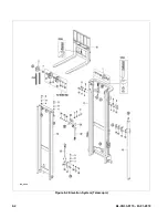
Страница 116: ...12 38 BL CB33 0115 03 01 2018 Figure 12 14 Elevation System Three Stage Mast DP_0009...
Страница 118: ...12 40 BL CB33 0115 03 01 2018 Figure 12 14 Elevation System Three Stage Mast Continued DP_0009...
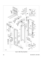
Страница 122: ...12 44 BL CB33 0115 03 01 2018 Figure 12 15 Lift Carriage Telescopic LIFT CARRIAGE TELESCOPIC DP_0013...
Страница 124: ...12 46 BL CB33 0115 03 01 2018 Figure 12 16 Lift Carriage Three Stage Mast DP_0014...
Страница 126: ...12 48 BL CB33 0115 03 01 2018 Figure 12 17 Side Shift Assembly DP_0034...
Страница 128: ...12 50 BL CB33 0115 03 01 2018 Figure 12 18 Chain Assembly DP_0017...
Страница 134: ...12 56 BL CB33 0115 03 01 2018 Figure 12 21 Hydraulic System Used with Side Shift DP_0036...
Страница 136: ...12 58 BL CB33 0115 03 01 2018 Figure 12 22 Tilt System DP_0015...
Страница 138: ...12 60 BL CB33 0115 03 01 2018 Figure 12 23 Lift System Telescopic Not with Side Shift DP_0019...
Страница 140: ...12 62 BL CB33 0115 03 01 2018 Figure 12 24 Lift System Telescopic With Side Shift DP_0037...
Страница 142: ...12 64 BL CB33 0115 03 01 2018 Figure 12 25 Lift System Three Stage Mast Not with Side Shift DP_0020...
Страница 144: ...12 66 BL CB33 0115 03 01 2018 Figure 12 25 Lift System Three Stage Mast with Side Shift DP_0038...
Страница 146: ...12 68 BL CB33 0115 03 01 2018 Figure 12 26 Lift Cylinder Telescopic DP_0010...
Страница 148: ...12 70 BL CB33 0115 03 01 2018 Figure 12 27 Free Lift Cylinder Three Stage Mast DP_0011...
Страница 150: ...12 72 BL CB33 0115 03 01 2018 Figure 12 28 Secondary Lift Cylinder Three Stage Mast DP_0012...
Страница 152: ...12 74 BL CB33 0115 03 01 2018 Figure 12 29 Tilt Cylinder Used up to Serial Number 324170306 DP_0016...
Страница 154: ...12 76 BL CB33 0115 03 01 2018 Figure 12 30 Tilt Cylinder Used from Serial Number 324170307 DP_0033...
Страница 156: ...12 78 BL CB33 0115 03 01 2018 Figure 12 31 Pump and Motor Not when Side Shift DP_0021...
Страница 158: ...12 80 BL CB33 0115 03 01 2018 Figure 12 32 Pump and Motor When Side Shift DP_0039...
Страница 160: ...12 82 BL CB33 0115 03 01 2018 Figure 12 33 Electrical System ELECTRICAL SYSTEM DP_0022...
Страница 162: ...12 84 BL CB33 0115 03 01 2018 Figure 12 34 Electrical Panel DP_0023...
Страница 164: ...12 86 BL CB33 0115 03 01 2018 Figure 12 35 Wire Harness Used up to Serial Number S2221337 DP_0024...
Страница 166: ...12 88 BL CB33 0115 03 01 2018 Figure 12 36 Wire Harness Used from Serial Number S2221338 DP_0040...
Страница 168: ...12 90 BL CB33 0115 03 01 2018 Figure 12 37 Wiring Cables DP_0025...
Страница 170: ...Big Lift LLC...