


4-18
BL-CB33-0115 - 03-01-2018
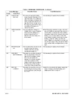
Table 4-3 STEERING CONTROLLER - Continued
Error Message
Possible Cause
Fault Elimination
Code
Error Text
244
GAIN EEPROM
KO
The parameters to compensate
for the gain of the current
amplifiers (ADJUSTMENT #03
and ADJUSTMENT #04 are
recorded in a not volatile mem-
ory (eeprom) with a redundant
handling. In fact every adjust-
ment is recorded in three
eeprom locations. If the values
in these thee location are dif-
ferent, this alarm occurs.
It is necessary to send the controller to Zapi to
execute the maximum current regulation.
246
MICRO SLAVE
KO
In stepper motor application, this
alarm occurs if the main uC is
detecting a direction of the
stepper motor not matched
with the one that the slave uC
is detecting.
In closed loop application, this
alarm occurs if the main uC is
detecting a direction of the
steering error not matched with
the one that the slave uC is
detecting.
Furthermore, this alarm occurs if
the main uC is detecting no
steering limitation meanwhile
the slave uC is detecting a
steering limitation.
It is necessary to replace the controller.
247
CAN BUS KO
This alarm occurs only when the
setting CAN BUS is PRESENT.
Then the EPS-AC0 must
receive the event messages
from the traction controller. If
these messages lack more
than about 1 sec, this alarm
occurs.
Check the CAN Bus communication system
and analyse the frames from the traction
controller to the steer controllers.
248
S.P OUT OF
RANGE
This alarm occurs for a fault on
the command potentiometer
(CPOC2on CNA#8). When a
single command pot is chosen,
the alarm occurs if the wiper
(CPOC1) exits the range from
0.8 Vdc to 4.2 Vdc. When the
twin pot is chosen, the alarm
occurs if the sum of the two
wiper voltages (CPOC1 +
CPOC2) exists the range from
4.5 Vdc to 5.5 Vdc.
Check the connections of the potentiometer.
This alarm occurs when one connection of
the command potentiometer is broken.
Содержание CB33
Страница 9: ...BL CB33 0115 03 01 2018 2 3 Figure 2 2 Sample of Operator Check List R6479...
Страница 12: ...2 6 BL CB33 0115 03 01 2018 NOTES...
Страница 18: ...3 6 BL CB33 0115 03 01 2018 NOTES...
Страница 38: ...4 20 BL CB33 0115 03 01 2018 NOTES...
Страница 44: ...5 6 BL CB33 0115 03 01 2018 NOTES...
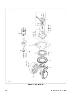
Страница 46: ...6 2 BL CB33 0115 03 01 2018 Figure 6 1 Drive Assembly DP_0004...
Страница 48: ...7 2 BL CB33 0115 03 01 2018 Figure 7 1 Drive Assembly DP_0004...
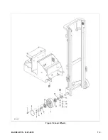
Страница 49: ...BL CB33 0115 03 01 2018 7 3 Figure 7 2 Load Wheels DP_0007...
Страница 50: ...7 4 BL CB33 0115 03 01 2018 NOTES...
Страница 52: ...8 2 BL CB33 0115 03 01 2018 Figure 8 2 Elevation System Telescopic DP_0008...
Страница 54: ...8 4 BL CB33 0115 03 01 2018 Figure 8 3 Mast Three Stage Mast DP_0009...
Страница 56: ...8 6 BL CB33 0115 03 01 2018 NOTES...
Страница 58: ...9 2 BL CB33 0115 03 01 2018 Figure 9 1 Hydraulic System DP_0018...
Страница 60: ...9 4 BL CB33 0115 03 01 2018 Figure 9 3 Elevation System Telescopic DP_0008...
Страница 66: ...9 10 BL CB33 0115 03 01 2018 Figure 9 8 Secondary Lift Cylinder Three Stage Mast DP_0012...
Страница 69: ...BL CB33 0115 03 01 2018 9 13 Figure 9 10 Tilt Cylinder DP_0016...
Страница 70: ...9 14 BL CB33 0115 03 01 2018 NOTES...
Страница 72: ...10 2 BL CB33 0115 03 01 2018 Figure 10 1 Electrical System R6478 DP_0022...
Страница 73: ...BL CB33 0115 03 01 2018 10 3 Figure 10 2 Electrical Panel R6478 DP_0023...
Страница 75: ...BL CB33 0115 03 01 2018 10 5 Figure 10 3 Transmission Motor Brake Assembly DP_0004...
Страница 76: ...10 6 BL CB33 0115 03 01 2018 NOTES...
Страница 77: ...BL CB33 0115 03 01 2018 11 1 SECTION 11 OPTIONAL EQUIPMENT...
Страница 78: ...11 2 BL CB33 0115 03 01 2018 NOTES...
Страница 80: ...12 2 BL CB33 0115 03 01 2018 Figure 12 1 Steering System DP_0001...
Страница 82: ...12 4 BL CB33 0115 03 01 2018 Figure 12 1 Steering System Continued DP_0001...
Страница 84: ...12 6 BL CB33 0115 03 01 2018 Figure 12 2 Control Head DPP_0002...
Страница 86: ...12 8 BL CB33 0115 03 01 2018 Figure 12 3 Control Head when Side Shift option DP_0035...
Страница 88: ...12 10 BL CB33 0115 03 01 2018 Figure 12 4 Drive System DP_0003...
Страница 90: ...12 12 BL CB33 0115 03 01 2018 Figure 12 5 Drive Assembly Used up to serial S2410419 DP_0004...
Страница 92: ...12 14 BL CB33 0115 03 01 2018 Figure 12 6 Drive Assembly Used between serial S2410420 and 325130600 DP_0028...
Страница 94: ...12 16 BL CB33 0115 03 01 2018 Figure 12 7 Drive Assembly Used from serial 325130601 DP_0032...
Страница 96: ...12 18 BL CB33 0115 03 01 2018 Figure 12 8 Gear Case Assembly Used between serial S2410420 and 326140869 DP_0029...
Страница 100: ...12 22 BL CB33 0115 03 01 2018 Figure 12 9 Gear Case Assembly Used from serial 326140870 DP_0042...
Страница 102: ...12 24 BL CB33 0115 03 01 2018 Figure 12 9 Gear Case Assembly Used from serial 326140870 Continued DP_0042...
Страница 104: ...12 26 BL CB33 0115 03 01 2018 Figure 12 10 Compartment DP_0005...
Страница 106: ...12 28 BL CB33 0115 03 01 2018 Figure 12 11 Frame DP_0006...
Страница 108: ...12 30 BL CB33 0115 03 01 2018 Figure 12 11 Frame Continued DP_0006...
Страница 110: ...12 32 BL CB33 0115 03 01 2018 Figure 12 12 Load Wheels DP_0007...
Страница 112: ...12 34 BL CB33 0115 03 01 2018 Figure 12 13 Elevation System Telescopic DP_0008...
Страница 114: ...12 36 BL CB33 0115 03 01 2018 Figure 12 13 Elevation System Telescopic Continued DP_0008...
Страница 116: ...12 38 BL CB33 0115 03 01 2018 Figure 12 14 Elevation System Three Stage Mast DP_0009...
Страница 118: ...12 40 BL CB33 0115 03 01 2018 Figure 12 14 Elevation System Three Stage Mast Continued DP_0009...
Страница 122: ...12 44 BL CB33 0115 03 01 2018 Figure 12 15 Lift Carriage Telescopic LIFT CARRIAGE TELESCOPIC DP_0013...
Страница 124: ...12 46 BL CB33 0115 03 01 2018 Figure 12 16 Lift Carriage Three Stage Mast DP_0014...
Страница 126: ...12 48 BL CB33 0115 03 01 2018 Figure 12 17 Side Shift Assembly DP_0034...
Страница 128: ...12 50 BL CB33 0115 03 01 2018 Figure 12 18 Chain Assembly DP_0017...
Страница 134: ...12 56 BL CB33 0115 03 01 2018 Figure 12 21 Hydraulic System Used with Side Shift DP_0036...
Страница 136: ...12 58 BL CB33 0115 03 01 2018 Figure 12 22 Tilt System DP_0015...
Страница 138: ...12 60 BL CB33 0115 03 01 2018 Figure 12 23 Lift System Telescopic Not with Side Shift DP_0019...
Страница 140: ...12 62 BL CB33 0115 03 01 2018 Figure 12 24 Lift System Telescopic With Side Shift DP_0037...
Страница 142: ...12 64 BL CB33 0115 03 01 2018 Figure 12 25 Lift System Three Stage Mast Not with Side Shift DP_0020...
Страница 144: ...12 66 BL CB33 0115 03 01 2018 Figure 12 25 Lift System Three Stage Mast with Side Shift DP_0038...
Страница 146: ...12 68 BL CB33 0115 03 01 2018 Figure 12 26 Lift Cylinder Telescopic DP_0010...
Страница 148: ...12 70 BL CB33 0115 03 01 2018 Figure 12 27 Free Lift Cylinder Three Stage Mast DP_0011...
Страница 150: ...12 72 BL CB33 0115 03 01 2018 Figure 12 28 Secondary Lift Cylinder Three Stage Mast DP_0012...
Страница 152: ...12 74 BL CB33 0115 03 01 2018 Figure 12 29 Tilt Cylinder Used up to Serial Number 324170306 DP_0016...
Страница 154: ...12 76 BL CB33 0115 03 01 2018 Figure 12 30 Tilt Cylinder Used from Serial Number 324170307 DP_0033...
Страница 156: ...12 78 BL CB33 0115 03 01 2018 Figure 12 31 Pump and Motor Not when Side Shift DP_0021...
Страница 158: ...12 80 BL CB33 0115 03 01 2018 Figure 12 32 Pump and Motor When Side Shift DP_0039...
Страница 160: ...12 82 BL CB33 0115 03 01 2018 Figure 12 33 Electrical System ELECTRICAL SYSTEM DP_0022...
Страница 162: ...12 84 BL CB33 0115 03 01 2018 Figure 12 34 Electrical Panel DP_0023...
Страница 164: ...12 86 BL CB33 0115 03 01 2018 Figure 12 35 Wire Harness Used up to Serial Number S2221337 DP_0024...
Страница 166: ...12 88 BL CB33 0115 03 01 2018 Figure 12 36 Wire Harness Used from Serial Number S2221338 DP_0040...
Страница 168: ...12 90 BL CB33 0115 03 01 2018 Figure 12 37 Wiring Cables DP_0025...
Страница 170: ...Big Lift LLC...