


ASSEMBLY (FOR ALL OTHER SAWS)
DISCONNECT THE SAW FROM THE POWER
SOURCE!
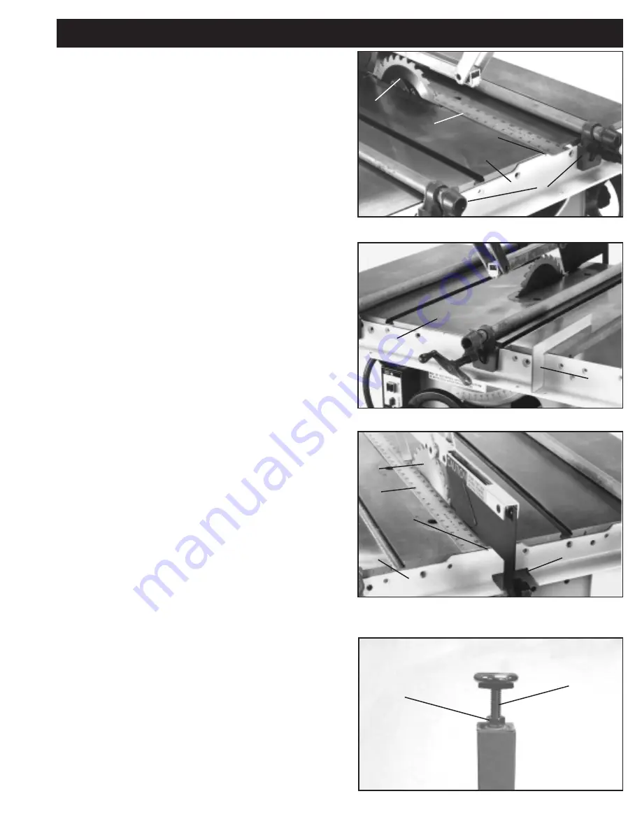
ASSEMBLE FRONT RAIL
1. Raise saw blade (A) Fig. 15. Place a straight edge (B)
against the right side of saw blade extending out over the
front of the saw as shown. Position front rail (C) against
the edge of saw table and lightly clamp in place using bar
clamps (D). Align notch (E) in front rail (C) with the straight
edge (B) as shown.
NOTE: Any portion of the notch
needs to align with the straight edge. Final
calibration will be explained later.
2. Using template (F) Fig. 16, check and adjust the front
rail at both sides of saw table, to make sure the horizontal
portion of front rail (C) is parallel with the table top and
then tighten bar clamps.
The rail should be down from
the top of the table 2-27/32”.
3. When you are certain front rail (C) is level with the table
surface, drill four 1/4” through holes into the saw table
using the 1/4” counter sunk holes in the front rail as a
template.
IMPORTANT: Before drilling, check to make
certain there is no interferance such as casting ribs
behind front edge of saw table.
4. Fasten front rail (C) to saw table using the four 1/4-20 x
1-1/4” long flat head screws, flat washers, lock washers
and hex nuts supplied.
ASSEMBLE REAR RAIL
5. Clamp rear rail (G) Fig. 17, to back of saw table using
bar clamps making certain notch (E) in rail is aligned with
saw blade (A) as shown, using straight edge (B). Make
sure the two cutouts in the rail are below the bottom of the
miter slots in the saw table.
6. Check to make certain there are no interferance such
as casting ribs behind the rear edge of the saw table and
drill a minimum of two through holes into the saw table
using the countersunk holes as a template. Fasten rear
rail to saw table using the 1/4-20 x 1-1/4” long flat head
screws, flat washers, lock washers and hex nuts supplied.
IMPORTANT: If there is no room in rear edge of the
table to drill through holes, it will be necessary to drill
#7 holes and tap holes with a 1/4-20 tap.
7. After fastening the rear rail to the saw table, tilt the saw
blade to make certain there is no interferance between
the saw guard and the rear rail. If there is, it will be
necessary to enlarge the cut-out (H) Fig. 17, in the rear
rail.
EXTENSION TABLE & SUPPORT LEGS
8. Assemble the 3/8” jam nut (I) onto leveling screw (J).
Thread leveling screw into foot adapter. Fig. 18 illustrates
the foot leveling assembly on the table leg. Assemble the
remaining foot assembly to the other leg in the same
manner.
NOTE: Height adjustments will be made later.
Fig. 16
Fig. 15
Fig. 17
Fig. 18
I
J
A
B
C
D
E
F
C
A
B
G
E
H
7


