background image

16

En

gl

is

h

17

En

gli

sh

User’s Manual UPSI-B-2410

1  

General Information and Safety Warnings ...............  5


1.1 

Contents of Delivery ....................................................................  5


1.2 

Optional Accessories ...................................................................  5

2  

Technical Data .........................................................  6


3  

Functional Description ...........................................  8


3.1 

Mains Mode ....................................................................................  8


3.2 

Battery Mode ..................................................................................  8


4  

LED Display ...............................................................9

5  

Installation and Commissioning .......................... 10

5.1 

DC Connector 1 ........................................................................... 11


5.2 

DC Connector 2 ........................................................................... 11


5.3 

Interface 9-pole Sub-D .............................................................. 12


5.4 

RUPS2000 OEM (UPS Software Package) ........................... 13


5.5 

Special Features of the UPSI-B-2410.................................... 14

6  

Manual Switch-Off 

(without UPS Management Software) .

 14

7  

Troubleshooting  .................................................   15

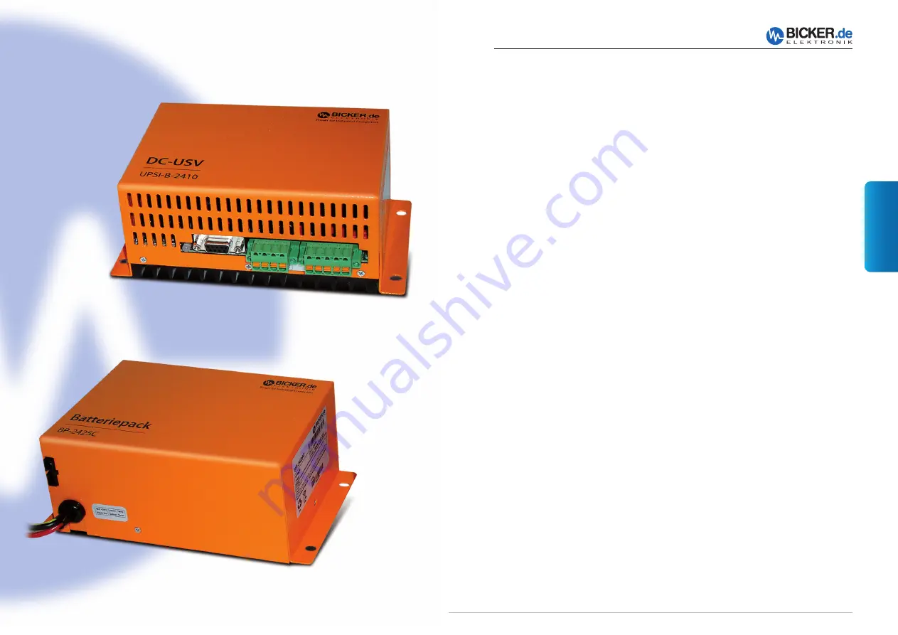
UPSI-B-2410

BP-2425C, optional accessory

Содержание UPSI-B-2410

Страница 1: ...USV Systeme Benutzerhandbuch User s Manual UPSI B 2410 Industrie PC Netzteile Netzteile Medizintechnik DC DC Wandler USV Systeme Systemkomponenten...

Страница 2: ...3 1 Netz Betrieb 8 3 2 Batterie Betrieb 8 4 LED Anzeige 9 5 Montage und Inbetriebnahme 10 5 1 DC Stecker1 11 5 2 DC Stecker2 11 5 3 Schnittstelle 9 polig Sub D 12 5 4 RUPS2000 OEM USV Softwarepaket 13...

Страница 3: ...werden Dabei sind die jeweiligen Vorschriften einzuhalten Am Eingang ist eine 15 A Sicherung vorzuschalten Alle Anschluss Leitungen m ssen dem max Eingangsstrom der UPSI B 2410 12 5 A entsprechend di...

Страница 4: ...densierend Lagerung 10 90 nicht kondensierend Abmessungen 182 x 102 x 73 mm 0 5 mm Gewicht 0 75 kg Produktspezifische Angaben LED Anzeige 3 Farben LED f r Power ok gr n Power Fail orange Battery low r...

Страница 5: ...C gemeldet werden 3 1 Netz Betrieb Im Netz Betrieb liefert eine vorgeschaltete Spannungsquelle 24VDC Diese Spannung abz glich 0 4VDC liegt direkt am Verbraucher z B PC an Der angeschlossene Batteriepa...

Страница 6: ...ratur F hler Batterie 3 Batterie 4 Batterie 5 2 DC Stecker 2 Anschluss Ein und Ausgang PIN 1 Ausgang 2 Eingang 3 Ausgang 4 Eingang 5 Erde Die Ausgangsspannung folgt der angeschlossenen Eingangs spannu...

Страница 7: ...meldungen Wichtige Grundeinstellungen 5 3 Schnittstelle 9 polig Sub D PIN PIN 1 n c 6 Shutdown Eingang 2 Power Fail Kollektor Ausgang 7 Bezug Shutdown 3 n c 8 n c 4 Bezug Power Fail Batterie Low Emitt...

Страница 8: ...g defekt Eingangssicherung erneuern Leitungsquerschnitt zu klein Empfohlener Leitungsquerschnitt 2 5 mm2 Der berspannungsschutz am Eingang ab 40 V DC hat angesprochen Die interne Supressor Diode schli...

Страница 9: ...Description 8 3 1 Mains Mode 8 3 2 Battery Mode 8 4 LED Display 9 5 Installation and Commissioning 10 5 1 DC Connector 1 11 5 2 DC Connector 2 11 5 3 Interface 9 pole Sub D 12 5 4 RUPS2000 OEM UPS So...

Страница 10: ...relevant rules of electrical engineering must be observed A 15 A fuse must be installed at input line All connector cables must be dimensioned for the max input current of the UPSI B 2410 12 5 A and a...

Страница 11: ...re Operating 30 70 C Storage 40 80 C Humidity Operating 10 85 non condensing Storage 10 90 non condensing Dimensions 182 x 102 x 73 mm 0 5 mm Weight 0 75 kg Product specific data LED display 3 colour...

Страница 12: ...via interface 3 1 Mains Mode In mains mode a voltage source at the input line supplies 24 VDC This voltage minus 0 4 VDC is provided directly at the consumer load e g PC The connected battery pack is...

Страница 13: ...mperature sensor battery 3 Battery 4 Battery 5 2 DC Connector 2 Input and output connection PIN 1 Output 2 Input 3 Output 4 Input 5 GND The output voltage corresponds to the connected input voltage mi...

Страница 14: ...Warnings Pop Up warning messages Important basic settings 5 3 Interface 9 pole Sub D PIN PIN 1 n c 6 Shutdown input 2 Power Fail collector output 7 Shutdown reference 3 n c 8 n c 4 Reference Power Fa...

Страница 15: ...fuse Cable cross section too small recommended cable cross section 2 5 mm2 The overvoltage protection at the input from 40 VDC was activated Short circuit of internal suppressor diode blows input fus...

Страница 16: ...30 English 31 English User s Manual UPSI B 2410 User s Manual UPSI B 2410 Notizen Notes Notizen Notes...

Страница 17: ...86609 Donauw rth Germany Tel 49 0 906 70595 0 Fax 49 0 906 70595 55 E Mail info bicker de www bicker de Irrt mer und technische nderungen vorbehalten Windows ist ein eingetragenes Warenzeichen der Fir...

Отзывы: