26
En
gl
is
h
27
En
gli
sh
User’s Manual UPSI-B-2410
User’s Manual UPSI-B-2410
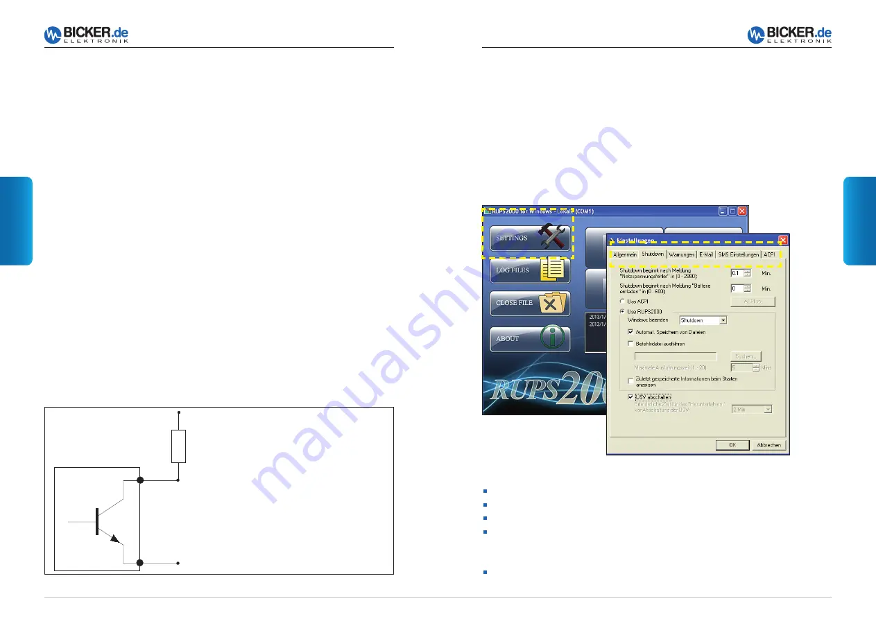
5.4 RUPS 2000 OEM (UPS Software Package)
The UPS software package supports the following operating systems of Windows®:
2000, 2003, XP, Vista, 7 and 8 (other OS upon request). The open collector interface
of the DC UPS module UPSI-B-2410 has been designed for the software RUPS 2000
OEM. A red interface cable (M2501) is included into the delivery of this software
package to connect the UPSI-B-2410 with a free COM-Port of a connected PC.
General
>> COM Port at PC
>> Sending e-mails via external e-mail server (not included in delivery)
Pager
>> Pager information on optional modem (not included in delivery)
Shutdown >> Back-up period, automatic storage of files, switch off UPS.
From version 3.21 the back-up period can be set in steps of
0.1 minutes (6 sec.).
Warnings >> Pop-Up warning messages
Important basic settings
5.3 Interface 9-pole Sub-D
PIN
PIN
1 n.c.
6 Shutdown input
2 Power Fail (collector) output
7 Shutdown reference
3 n.c.
8 n.c.
4 Reference Power Fail, Battery Low (emitter)
9 n.c.
5 Battery Low (collector) output
Power Fail
In mains mode, the collector-emitter-line of the optocoupler is “nonconducting“. In
battery mode (input voltage <20 V DC), the collector-emitter-line of the optocoupler
is “conductive“.
Battery Low
In mains mode, the collector-emitter-line of the optocoupler is “nonconducting“. In
battery mode and with low battery voltage (<21 V DC) the collector-emitter-line of the
optocoupler is “conductive“.
Shutdown
When a voltage of +5...24 V DC is supplied at PIN6 during battery mode and after 2
minutes of shutdown suppression (see 5.5), the UPSI-B-2410 switches off after app.
5 seconds.
Power Fail
PIN2
Power Fail (reference)
PIN4
UPSI-B-2410
Interface
(+)
For a digital output (SPS) a “Pull-UP“
resistance can be determined.
Data of optocoupler:
Uce
24 V DC
Ice
0.1 Amax
P
0.1 Wmax


