User’s Manual UPSI-B-2440
Bicker Elektronik GmbH
||
Tel. +49 (0)906 70595-0
||
www.bicker.de
||
25
E
n
g
li
sh
Notes
The DC input (DC connector, PIN 5) must be protected by a 50 A fuse.
Observe the correct polarity when connecting the battery pack BP-2450C
as well as the inputs and outputs!
Before switching on the unit, make sure all connections are correct.
All fuses, especially that of the battery pack, must be engaged.
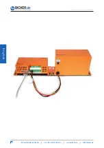
5.1 TEMP connector: Battery pack temperature sensor connection
At this pin-and-socket connector the temperature sensor of the battery pack
BP-2450C is connected.
PIN
1 Temperature sensor battery
2 Temperature sensor battery
5.2 DC connector: Battery, input and output connection, ground
PIN
1 Battery (+)
2 Battery (–)
3 Output (+)
4 Output (–)
5 Input (–)
6 Input (+)
7 GND
5.3 LED connector (optional)
PIN
1 GND
2 Green
3 Red
4 n.c.
The output voltage corresponds to the connected input
voltage minus 0.4 V DC.
1 2


