User’s Manual UPSI-B-2440
Bicker Elektronik GmbH
||
Tel. +49 (0)906 70595-0
||
www.bicker.de
||
26
E
n
g
lis
h
5.4 Interface 9-pole Sub-D
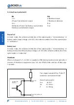
PIN
PIN
1 n.c.
6 Shutdown input
2 Power Fail (collector) output
7 Shutdown reference
3 n.c.
8 n.c.
4 Reference Power Fail, Battery Low (emitter)
9 n.c.
5 Battery Low (collector) output
Power Fail
In mains mode, the collector-emitter-line of the optocoupler is “nonconducting“. In
battery mode (input voltage <20 V DC), the collector-emitter-line of the optocoupler
is “conductive“.
Battery Low
In mains mode, the collector-emitter-line of the optocoupler is “nonconducting“. In
battery mode and with low battery voltage (<21 V DC) the collector-emitter-line of the
optocoupler is “conductive“.
Shutdown
When a voltage of +5...24 V DC is supplied at PIN6 during battery mode and after 2
minutes of shutdown suppression (see 5.6), the UPSI-B-2440 switches off after app.
5 seconds.
Power Fail
PIN2
Power Fail (reference)
PIN4
UPSI-B-2440
Interface
(+)
For a digital output (SPS) a “Pull-UP“
resistance can be determined.
Data of optocoupler:
Uce
24 V DC
Ice
0.1 Amax
P
0.1 Wmax


