background image

User’s Manual UPSI-B-2440

Bicker Elektronik GmbH

    ||   

Tel. +49 (0)906 70595-0

    ||   

www.bicker.de

    ||   

[email protected]

22

E

n

g

lis

h


3  Functional Description

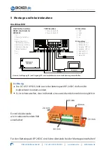
In  case  of  a  mains  voltage  failure  the  DC  UPS  UPSI-B-2440  supplies  the  connected  
consumer load with DC voltage from the connected battery pack. Via LED display the 
status is visualised. Signals can be informed to a connected PC via interface.

3.1  Mains Mode
In mains mode a voltage source at the input line supplies 24 V DC. This voltage minus 
0.4 V DC is provided directly at the consumer load (e. g. PC). The connected battery 
pack  is  charged  by  the  UPSI-B-2440.  The  LED  is  green  and  the  interface  signalises 
“Power  ok“.  App.  every  10  minutes  a  battery  test  is  carried  out.  In  case  of  a  defect  
battery or if the battery pack is not connected, the LED flashes red/green.

3.2  Battery Mode
If  the  supply  voltage  drops  below  the  switch-over  threshold  at  the  input  of  the  
DC  UPS  UPSI-B-2440,  the  UPSI-B-2440  takes  over  supplying  the  connected  consu-
mer  loads.  The  LED  is  orange  and  the  interface  signalises  “Power  Fail“.  When  the 
capacitance  of  the  connected  battery  pack  decreases  (battery  voltage  dropping  to    
<21 V), the interface signalises “Battery Low“. The LED flashes red/orange. The DC UPS  
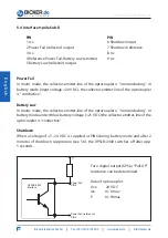
UPSI-B-2440 can be switched off by an impulse at the “Shutdown“ input.

AC

DC

DC UPS

UPSI-B-2440

Consumer 

load (PC)

Interface

Battery

pack 

BP-2450C

Source:  

e. g. AC/DC power supply

50 A

Содержание BP-2450C

Страница 1: ...USV Systeme Benutzerhandbuch User s Manual UPSI B 2440 Industrie PC Netzteile Netzteile Medizintechnik DC DC Wandler USV Systeme...

Страница 2: ...UPSI B 2440 BP 2450C optionales Zubeh r...

Страница 3: ...iches Zubeh r 5 2 Technische Daten 6 3 Funktionsprinzip 8 3 1 Netz Betrieb 8 3 2 Batterie Betrieb 8 4 LED Anzeige 9 5 Montage und Inbetriebnahme 10 5 1 TEMP Anschluss 11 5 2 DC Anschluss 11 5 3 LED An...

Страница 4: ...Benutzerhandbuch UPSI B 2440 Bicker Elektronik GmbH Tel 49 0 906 70595 0 www bicker de info bicker de 4...

Страница 5: ...personal durchgef hrt werden Dabei sind die jeweiligen Vorschriften einzuhalten Am Eingang ist eine 50 A Sicherung vorzuschalten Alle Anschluss Leitungen m ssen dem max Eingangsstrom der UPSI B 2440 4...

Страница 6: ...are zur Anbindung an g ngige Betriebssysteme lieferbar Batterietyp Blei Zinn Batterie wartungsfrei Sicherheit EMV CE Umgebungstemperaturbereich 30 70 C Lagertemperaturbereich 40 80 C Lagerfeuchtigkeit...

Страница 7: ...54 0 mm 25 0 mm 103 0 mm 76 0 mm 204 0 mm 1 0 mm 234 0 mm 3 BAT BAT OUT OUT IN IN 1 2 4 5 6 7 Umschaltung auf Schnell Ladung Ladeschluss spannung Ladespannung Trickle Charge I Umschaltung auf Erhaltun...

Страница 8: ...e LED leuchtet gr n und die Schnittstelle signalisiert Power ok Etwa alle 10 Minuten wird ein Batterietest durch gef hrt Bei defektem Akku oder z B nicht angeschlossenem Batteriepack blinkt die LED ro...

Страница 9: ...LED leuchtet orange sobald die DC USV UPSI B 2440 in den Batterie Betrieb schaltet Eingangsspannung 20 V DC LED rot orange blinkend Die LED blinkt im Batterie Betrieb rot orange wenn die Kapazit t de...

Страница 10: ...Power Fail Kollektor 3 n c 4 Bezug Power Fail Batterie Low Emitter 5 Batterie Low Kollektor 6 Shutdown Eingang 7 Bezug Shutdown 8 n c 9 n c LED Anschluss 1 GND 2 Gr n 3 Rot 4 n c DC Anschluss 1 Batter...

Страница 11: ...llen Alle Sicherungen m ssen gesteckt sein insbesondere auch die des Batteriepacks 5 1 TEMP Anschluss Anschluss Batteriepack Temperatursensor An diesen Steckverbinder wird der Temperatursensor des Bat...

Страница 12: ...Kollektor Emitter Strecke des Optokopplers leitend Batterie Low Im Netz Betrieb ist die Kollektor Emitter Strecke des Optokopplers nicht leitend Im Batterie Betrieb und schwacher Batteriespannung 21 V...

Страница 13: ...EM konzipiert Diesem Softwarepaket liegt ein rotes Schnittstellen Kabel M2501 bei Damit kann die UPSI B 2410 mit einem freien COM Port eines angeschlossenen PC s verbunden werden General COM Port am P...

Страница 14: ...ist kein Bedienereingriff notwendig Shutdown Unterdr ckung Das Shutdown Signal wird in der Startphase des Systems f r ca 2 Minuten unterdr ckt da eine eventuelle Schnittstellenpr fung von Windows und...

Страница 15: ...ettings Shutdown und USV abschalten wurde nicht gesetzt Die Shutdown Unterdr ckungszeit Punkt 5 5 wurde nicht abgewartet und somit wurde der Shutdown Impuls unterdr ckt Das Schnittstellenkabel ist def...

Страница 16: ...UPSI B 2440 BP 2450C optional accessory...

Страница 17: ...es 19 2 Technical Data 20 3 Functional Description 22 3 1 Mains Mode 22 3 2 Battery Mode 22 4 LED Display 23 5 Installation and Commissioning 24 5 1 TEMP connector 25 5 2 DC connector 25 5 3 LED conne...

Страница 18: ...User s Manual UPSI B 2440 Bicker Elektronik GmbH Tel 49 0 906 70595 0 www bicker de info bicker de 18 En g lish...

Страница 19: ...missioning must only be carried out by qualified personnel The relevant rules of electrical engineering must be observed A 50 A fuse must be installed at input line All connector cables must be dimens...

Страница 20: ...also with UPS software for connecting all established operating systems Type of battery Maintenance free pure lead tin battery PLT Safety EMC CE Operating temperature 30 70 C Storage temperature 40 8...

Страница 21: ...5 5 m m DC USV UPSI B 2440 254 0 mm 25 0 mm 103 0 mm 76 0 mm 204 0 mm 1 0 mm 234 0 mm 3 BAT BAT OUT OUT IN IN 1 2 4 5 6 7 Start of fast charging End of charging voltage Charging voltage Trickle charge...

Страница 22: ...0 The LED is green and the interface signalises Power ok App every 10 minutes a battery test is carried out In case of a defect battery or if the battery pack is not connected the LED flashes red gree...

Страница 23: ...nge The LED turns to orange as soon as the DC UPS UPSI B 2410 switches to battery mode input voltage 20 VDC LED red orange flashing The LED flashes red orange in battery mode when the capacitance of t...

Страница 24: ...nstalling a fuse on site at both the input F1 and output F2 is recommended Interface connector DSUB9 interface for RUPS2000 1 n c 2 Power Fail collector 3 n c 4 Reference Power Fail Battery low Emitte...

Страница 25: ...rect All fuses especially that of the battery pack must be engaged 5 1 TEMP connector Battery pack temperature sensor connection At this pin and socket connector the temperature sensor of the battery...

Страница 26: ...20 VDC the collector emitter line of the optocoupler is conductive Battery Low In mains mode the collector emitter line of the optocoupler is nonconducting In battery mode and with low battery voltag...

Страница 27: ...designed for the software RUPS 2000 OEM A red interface cable M2501 is included into the delivery of this software package to connect the UPSI B 2410 with a free COM Port of a connected PC General CO...

Страница 28: ...ervention of the user is required Shutdown Suppression The shutdown signal is suppressed for about 2 minutes while the system is starting up since a possible interface check of Windows with a simultan...

Страница 29: ...000 OEM The checkmark under Settings Shutdown and Switch off UPS USV abschalten was not set The shutdown suppression period see 5 5 was disturbed and the shutdown impulse was thus suppressed The inter...

Страница 30: ...User s Manual UPSI B 2440 Bicker Elektronik GmbH Tel 49 0 906 70595 0 www bicker de info bicker de 30 En g lish Notizen Notes...

Страница 31: ...User s Manual UPSI B 2440 Bicker Elektronik GmbH Tel 49 0 906 70595 0 www bicker de info bicker de 31 En g lish Notizen Notes...

Страница 32: ...Tel 49 0 906 70595 0 Fax 49 0 906 70595 55 E Mail info bicker de Internet www bicker de Irrt mer und technische nderungen vorbehalten Windows ist ein eingetragenes Warenzeichen der Firma Microsoft Co...

Отзывы: