Biasi RIVA COMPACT HE MK2 M96A.24SR/C Скачать руководство пользователя страница 4

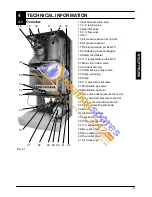
Boiler installation and commissioning tips

n

The installation

must be carried out by

a qualified person who will be responsible for

observing the current Regulations.

Installing the boiler...

n

Do not forget to remove the transit caps

and plugs from the boiler connections these

are fitted to every boiler.

n

Keep the boiler clear of dust during in-

stallation and in particular do not allow any

dust or debris to enter the top of the boiler

where the flue connection is made. It is rec-

ommended that you put a dust sheet over the

top of the boiler until you are ready to make

the flue connection.

n

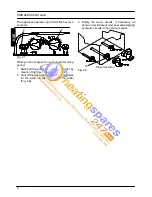
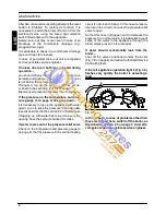
Because every boiler is fired and tested

live at the factory, a small amount of water re-

mains within the boiler. It is possible for this

water to initially cause the pump to seize. It is

therefore recommended that the pump rotor

be manually turned to free its rotation before

turning the boiler on.

n

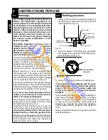
Remember to release the auto air purge

before filling the boiler. See the instructions to

identify the location of this device.

n

Do not remove the cap of the pressure

test points of the air switch (top left side of the

boiler).

n

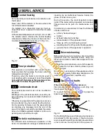
You are strongly advised to flush out the

system both cold and hot in order to remove

system and installation debris.

n

It is also sensible to initially fire and com-

mission the boiler before connecting any ex-

ternal controls such as a room thermostat. By

this method if you have a subsequent prob-

lem following the addition of an external con-

trol you can eliminate the boiler from your

fault analysis.

n

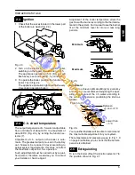
Do not forget to range rate the boiler to

suit the system requirements. This pro-

cedure is covered in the commissioning sec-

tion of the installation manual.

n

If the boiler is fitted with a digital pro-

grammer, when setting the times for auto-

matic operation, remember that for every

“ON” time there must be an “OFF” time to fol-

low and that on every occasion you enter a

time you must also indicate which days that

you want the boiler to follow the timed set-

tings.

n

Some products incorporate an anti cycl-

ing time delay. It is normal when first switch-

ing the boiler on for the boiler to operate on

heating for a few seconds then switch off.

After 3--- 4 minutes has elapsed the boiler will

then re ignite and operate perfectly normally.

The ignition delay cycle does not prevent

normal operation of the boiler to provide

d.h.w.

n

If you are in any doubts as to the installa-

tion or operation of the boiler please read the

instruction manuals thoroughly and then if

necessary contact Biasi UK for advice and

assistance.

Please remember that if you are in any doubt about the installation of this product you can contact our

Technical Helpline on tel. 0121 506 1350

Содержание RIVA COMPACT HE MK2 M96A.24SR/C

Страница 1: ...tallation instructions RIVA COMPACT HE MK2 Models M96A 24SR C System boiler M96A 28SR C System boiler U n i t 3 A T h o r n t o n R o a d I n d E s t a t e O f f H o c k n e y R o a d B r a d f o r d...

Страница 2: ...low to the boiler is fitted with all the safety and control de vices required by the current Regulations n Ensure that the installer has connected the pressure relief valve outlet to a drain pipe The...

Страница 3: ...ng contact lenses Irritation to respiratory tract Precautions Dust goggles will protect eyes People with a history of skin complaints may be particularly susceptible to irritation High dust le vels ar...

Страница 4: ...ex ternal controls such as a room thermostat By this method if you have a subsequent prob lem following the addition of an external con trol you can eliminate the boiler from your fault analysis n Do...

Страница 5: ...Choice of flue 22 6 9 Electrical connections 25 6 10 External frost protection 26 6 11 Connecting a system boiler to a cylinder 27 7 Commissioning 30 7 1 Electrical installation 30 7 2 Gas supply inst...

Страница 6: ...e normal oper ation of the boiler It must be used only by a qualified person during commissioning and servicing 1 3 Isolation valves 12 11 13 10 Fig 1 2 bottom view of the boiler 10 Condensate drain p...

Страница 7: ...y air pressure sensor Lack of burner ignition no ignition signal from the full seqence ignition device Safety thermostat lock out Flue temperature probe NTC lock out Flame detection error Other faults...

Страница 8: ...nce is provided with a built in anti freeze system that operates the boiler when the temperature is below 5 C Therefore when the boiler is not lit or used in cold weather with consequent risk of freez...

Страница 9: ...ts must be carried out by a quali fied person therefore we advise you to contact your installer or Service Agent Adjustment of the boiler temperature alters the gas flow at the burner according tothe...

Страница 10: ...ch 2 Shut off the gas supply cock 12 and the valves for the water circuits fitted under the boiler Fig 2 8 3 Empty the water circuits if necessary as shown in section General access andemptying hydrau...

Страница 11: ...oiler it is advisable to arrange maintenance and cleaning by an Authorised Service Centre En gineer at least once a year During the service the most important compo nents of the boiler will be inspect...

Страница 12: ...velas described in the section 2 2of thismanual If topping up with water has to be done very fre quently have the system checked for leaks If water comes out of the pressure relief valve Check on the...

Страница 13: ...ger valve 24 Pump vent plug 25 Pump 26 C h pressure relief valve 27 Modulation gas valve 28 Modulation operator 29 Gas valve outlet pressure test point 30 Gas valve inlet pressure test point 31 Primar...

Страница 14: ...29 25 26 27 30 23 38 11 13 12 37 14 32 20 28 19 33 21 18 22 10 17 Fig 4 2 INSTALLATION U n i t 3 A T h o r n t o n R o a d I n d E s t a t e O f f H o c k n e y R o a d B r a d f o r d B D 8 9 H Q 0 1...

Страница 15: ...of water through the primary heat exchanger 4 4 Expansion vessel Note this boiler is designed for operation only in a sealed central heating system The height difference between the pressure relief va...

Страница 16: ...17 2 000 20 2 500 25 1 mbar approximately equals 10 mm H2O Gas pressures at the burner Gas Natural G20 Butane G30 Propane G31 Max Pa mbar 1130 11 3 2810 28 1 3610 36 1 Min Pa mbar 250 2 5 580 5 8 780...

Страница 17: ...t temperature D C 71 Mass flow rate D g s 16 0 Flue gas figures Nominal heat input A D kW 25 0 CO2 content 6 5 O2 content 9 3 CO content ppm 75 Exhaust temperature D C 71 NOx class 2 Weighted NOx ppm...

Страница 18: ...17 2 000 20 2 500 25 1 mbar approximately equals 10 mm H2O Gas pressures at the burner Gas Natural G20 Butane G30 Propane G31 Max Pa mbar 1130 11 3 2810 28 1 3600 36 0 Min Pa mbar 240 2 4 580 5 8 780...

Страница 19: ...t temperature D C 69 Mass flow rate D g s 17 8 Flue gas figures Nominal heat input A D kW 29 0 CO2 content 6 8 O2 content 8 8 CO content ppm 52 Exhaust temperature D C 69 NOx class 2 Weighted NOx ppm...

Страница 20: ...lectrical provisions of the Building Regulations applicable in Scotland with respect to the installation of the combined appliance in a room containing a bath or shower For Ireland IE reference should...

Страница 21: ...the boiler inlet connection should not be used Installation pipes should be fitted in accordance with BS 6891 and the complete installation should be tested for tightness For Ireland IE refer to I S...

Страница 22: ...uilt in automatic air release valve it should be ensured as far as possible that the appliance heat exchanger is not a natural col lecting point for air Except where providing useful heat pipes should...

Страница 23: ...dues swarfs oils and other installation de bris is removed Where a new boiler is fitted to an existing system it is important the debris from the existing system is fully removed in order to ensure th...

Страница 24: ...minimum gaps indicated in Fig 6 1 25 50 250 200 Fig 6 1 all dimensions in mm When installing the boiler in a cupboard cover or alcove allow at least50mm permanentclear ance from the front face of the...

Страница 25: ...ke the protective caps off the boiler pipe work 2 Thoroughly clean the connections 3 Mount the boiler on its bracket 4 Fix the c h valves A and gas cock B to the boiler using the gaskets Fig 6 3 5 Fix...

Страница 26: ...scharge horizontally it is not de signed to enable termination in the vertical plane Vertical kit with 90 elbow Fig 6 6B Co axial 60 100 mm Supplied with a straight flanged adapter a co axial elbow an...

Страница 27: ...rs with different size are supplied with the twin pipe kit and have to be installed between the boiler and the air intake adapter Fig 6 10 Air intake adapter Restrictor Gasket Fig 6 10 For the correct...

Страница 28: ...rough a telescopic co axial flue 450 950 mm In the last section the fumes are expelled through a vertical section Extensions and elbows can be added to extend the kit s length 90 1 m 45 0 5 m 90 0 85...

Страница 29: ...switch to the power supply terminal block of the boiler Fig 6 17 keeping the same connections for the live brown wire and the neutral blue wire External 3 A fuseor fused plug with same current rating...

Страница 30: ...trol flexible cord as illustrated in Fig 6 20 Lock the flexible cords in place with the flexible cord clamps To the fused spur To the external control device isolation switch Fig 6 20 6 10 External fr...

Страница 31: ...must be connected to The lower part shows how to realize a system that provides independent timed and thermostatic control of heating and hot water In Fig 6 23 the boiler is permanently connected to...

Страница 32: ...V a c Switched 3 Amp fused spur L N 2 3 1 Programmer HTG HW OFF HW ON L N 2 1 4 6 7 Power supply L N 2 3 1 1 2 3 External control terminal block 8 10 way junction box Valve colour key WH White GRYE Gr...

Страница 33: ...Switched 3 Amp fused spur L N 2 3 1 Programmer HTG HW OFF HW ON L N 2 1 4 6 7 Power supply L N 2 3 8 External control terminal block 10 way junction box Mid position diverter valve HTG Heating HW ON H...

Страница 34: ...n the appliance and check the gas connector on the appliance for leaks Open position 12 Fig 7 1 7 3 Initial filling of the system 1 Open the c h flow and return valves 2 Remove the front panel of the...

Страница 35: ...heat 1 Turn on the electricity supply to the boiler switching on the fused spur isolation switch The appliance operation light 9 will flash every 4 seconds 2 Turn the function selector 7 as in Fig 7 3...

Страница 36: ...e checked and adjusted if necessary Important after the gas pressure checks and any adjustmentoperations allof the testpoints and adjustment devices must be sealed Re place the adjustment protection c...

Страница 37: ...grity of the conden sate drain pipe Verify the cleanness and correct filling of the con densate traps 7 11 Instructing the user Hand over this combined User Installation man ual and the Servicemanual...

Страница 38: ...Carry out the conversion for the type of gas re placing the burner injectors correctly 6 Re assemble the burner the front panel of the combustion chamber 7 Switch on the appliance at the mains isolati...

Страница 39: ...eration turn it ON by the function selector 7 on the desired operation and checking the ignition pressure and that the burner lights up uniformly In any case the boiler automatically resets to its nor...

Страница 40: ...ce and turn off the gas cock before carrying out any pro cedures whatsoever for cleaning mainten ance opening or dismantling boiler panels 9 2 Dismantling the external panels Front panel A Sampling po...

Страница 41: ...it is sufficient to dust it with a bristle paintbrush To reach the burner 1 Take off the front of the case 2 Take off the removable front of the sealed chamber and thefront panelof thecombustion chamb...

Страница 42: ...U n i t 3 A T h o r n t o n R o a d I n d E s t a t e O f f H o c k n e y R o a d B r a d f o r d B D 8 9 H Q 0 1 2 7 4 4 8 8 3 8 8 w w w h e a t i n g s p a r e s 2 4 7 c o m...

Страница 43: ...U n i t 3 A T h o r n t o n R o a d I n d E s t a t e O f f H o c k n e y R o a d B r a d f o r d B D 8 9 H Q 0 1 2 7 4 4 8 8 3 8 8 w w w h e a t i n g s p a r e s 2 4 7 c o m...

Страница 44: ...o 0121 506 1340 Sales Fax No 0121 506 1360 Service Tel No 0121 506 1350 Service Fax No 0121 506 1370 www biasi co uk 03 12 2008 N U n i t 3 A T h o r n t o n R o a d I n d E s t a t e O f f H o c k n...

Отзывы: