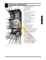


Installation
22
6.7
Fitting the flue system
Refer to the assembly instructions contained with-
in the chosen flue kit packaging for the correct as-
sembly and installation.
In general, it has to be taken in consideration that
the horizontal sections of the flue pipe must have
an horizontal sloping not less than 1.5 deg. (25
mm per metre) towards the boiler.
In the standard horizontal flue kit (Fig. 6.6A) the
flue pipe is angled within the air duct therefore the
air duct must be horizontally installed.
If one or more extensions have to be used they
must be adequately supported so that there is no
sag in the flue pipe and a minimum fall of 1,5 deg.
(25 mm per metre) over the whole length towards
the boiler is ensured.
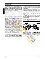
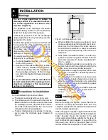
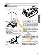
Before fitting the flue system, ensure that the flue
gasket shown in Fig. 6.5 (given with the boiler) is
fitted to the boiler.
Fig. 6.5
6.8
Choice of flue
The following flue kits are available for connecting
to the boiler:
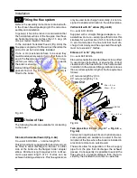
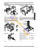
Standard horizontal flue kit (Fig. 6.6A)
Co---axial 60/100mm --- nominal length 1m
This kit is normally supplied with the boiler and can
be fitted to allow discharge to the rear or either
side of the boiler via the flanged boiler adapter
elbow. Minimum length required is 0.3 m. Maxi-
mum equivalent length of 2,7 metres can be
achieved utilising extensions. This flue system can
only be used to discharge horizontally, it is not de-
signed to enable termination in the vertical plane.
Vertical kit with 90
˚
elbow (Fig. 6.6B)
Co---axial 60/100 mm
Supplied with a straight flanged adapter a co---
axial elbow and a co---axial pipe with terminal, this
kit allows for a vertical rise of 0,5 m from the boiler.
In all circumstances the flue terminal must dis-
charge horizontally and the equivalent flue length
must not exceed 2,7 metres.
Elbows 45
˚
& 90
˚
(Fig. 6.6C)
Co---axial 60/100mm.
Elbow kits enable the standard flue kits to be offset
to overcome obstructions or ensure the correct
clearances for the flue terminal. Each elbow used
in addition to the standard flanged elbow reduces
the overall acceptable length of the flue system as
follows:
45
˚
reduce length by 0,5 m.
90
˚
reduce length by 1 m.
ø 60/100
ø 60/100
90
˚
=--- 1 m
45
˚
=--- 0,5 m
A
B
C
Min = 0,3 m
Max = 2,7 m
Type C12
Fig. 6.6
Twin pipe kits ø 80 mm (Fig. 6.7 --- Fig. 6.8 ---
Fig. 6.9)
Various twin (split) pipes kits and optional acces-
sories (elbows) are available to assist in the ter-
mination of the flue where the boiler is installed in
a location remote to an outside wall.
These kits allow for separation of the air supply
pipe from the pipe that discharges the exhaust
gasses. Consequently it is possible to extend the
flue system to a greater distance than that pro-
vided by the standard horizontal co---axial flue.
IN
S
TA
LLA
TI
O
N