


Commissioning
33
7 If the ignition pressure recorded is not as indi-
cated in the Technical Data then refer to section
“Ignition gas pressure adjustment” of the Ser-
vice Manual for the necessary adjustment pro-
cedures.
Important: after the gas pressure checks and
any adjustment operations, all of the test points
must be sealed and replace the adjustment
protection cap.
7.8
Checking the ignition device
With the burner on high flame close the gas cock.
After three ignition attempts (within about three
minutes), the lock---out signal lamp 5 (Fig. 1.3 on
page 2) must appear.
To reset the boiler press and release the boiler
reset button 6 (Fig. 1.3 on page 2).
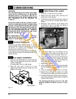
7.9
Checking the flue system
The flue system should be visually checked for
soundness. Check all clamps, gaskets and fixing
are secure and tight.
Ensure that the flue terminal is sited correctly in ac-
cordance with the flue fitting instructions and
Fig. 5.1 on page 17 of this manual.
To carry out a combustion check refer to the in-
structions given in the section 9.4 of this manual.
Reference figures are given in the sections 4.5 or
4.6 of this manual (Flue gas figures).
7.10
Checking the condensate
drain pipe
Check the soundness and integrity of the conden-
sate drain pipe.
Verify the cleanness and correct filling of the con-
densate traps.
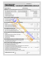
7.11
Instructing the user
Hand over this combined User & Installation man-
ual and the Service manual to the end user and ex-
plain how to use the unit.
Take the User step by step through the lighting in-
structions.
Show the User how to switch off the appliance
quickly and indicate the position of the electric
supply isolator.
Explain the proper use and adjustment of all sys-
tem controls; this will ensure the greatest possible
fuel economy.
Explain the function and use of the function selec-
tor.
Explain and demonstrate the function of time and
temperature controls (if fitted).
Explain how to turn off the appliance for both short
and long periods and advise on the precautions
necessary to prevent damage should the
appliance be inoperative when freezing condi-
tions may occur.
Fill in the details required on the Boiler Guarantee
Certificate and hand to the User advising them to
return the correct section for boiler Guarantee reg-
istration.
Finally, advise the User that, for continued safe
and efficient operation, the appliance must be ser-
viced by a competent person at least once a year.
IN
S
TA
LLA
TI
O
N