


4
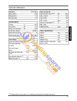
TECHNICAL INFORMATION
9
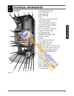
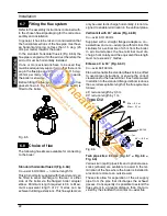
4.1
Overview
21
36
35
34
33
31
32
23
18
14
25
16
15
24
27
17
19
20
22
26
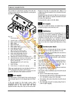
Fig. 4.1
10 Condensate drain pipe
11 C.h. return valve
12 Gas inlet valve
13 C.h. flow valve
14 Fan
15 Air pressure sensor test points
16 Air pressure sensor
17 Flue temperature probe NTC
18 Condensing heat exchanger
19 Safety thermostat
20 C.h. temperature probe NTC
21 Main circuit drain valve
22 Condensate trap
23 Automatic air purger valve
24 Pump vent plug
25 Pump
26 C.h. pressure relief valve
27 Modulation gas valve
28 Modulation operator
29 Gas valve outlet pressure test point
30 Gas valve inlet pressure test point
31 Primary circuit pressure switch
32 Flame---detecting electrode
33 Burner
34 Ignition electrodes
35 Combustion chamber
36 Primary heat exchanger
37 C.h. expansion tank
38 By---pass valve
39 Fan pressure connection
40 Flue outlet pipe
41 Air intake pipe
IN
S
TA
LLA
TI
O
N