background image

36

18

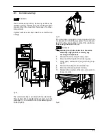
Ignition and detection electrodes

18.1

Function

Three electrodes are fitted on the burner. Two of them

are the ignition electrodes and are fitted near the front

part of the burner. The ignition sparks take place be-

tween their metallic edges over the central ramp of the

burner during the ignition sequence.
The third electrode is the detection electrode and it de-

tects the presence of the flame.

Ignition

Detection

Male

Female

Fig. 81

18.2

Checks

n

Check the position of the electrode edges

Warning: isolate the boiler from the mains

electricity supply before removing any

covering or component.

1

Remove all the case panels, the sealed chamber

lid and the combustion chamber lid.

2

Check for the correct distance between the me-

tallic edges of the ignition electrodes (see

Fig. 82).

Ignition

4 mm

Fig. 82

3

Check the integrity of the detection electrode and

ensure that its metallic edge is correctly placed

over the ramp of the burner.

n

Check the connection wires.

Warning: isolate the boiler from the mains

electricity supply before removing any

covering or component.

1

Remove all the case panels, the sealed chamber

lid and the combustion chamber lid.

2

Check for the integrity of the insulation of wires

which connect the electrodes to the ignition de-

vice.

18.3

Removal

Warning: isolate the boiler from the mains

electricity supply before removing any

covering or component.

1

Remove all the case panels, the sealed chamber

lid and the combustion chamber lid.

2

Disconnect the electrode wires from the full se-

quence ignition device.

3

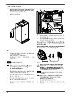
Remove the plate C (see Fig. 85 on page 37).

4

Remove the burner by unscrewing the four

screws placed at the right and left sides of the

burner.

5

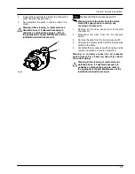
Unscrew the screws

A

(Fig. 83) which hold the

electrodes to the burner.

A

Fig. 83

6

Extract the electrodes from the burner.

7

Assemble the electrodes carrying out the removal

operation in reverse order.

Refer to Fig. 81 in order to recognise the elec-

trodes and to correctly connect the wiring.

Note: the metallic edge of the detection electrode is

longer than the one of the ignition electrodes.

Warning: After cleaning or replacement as

detailed above, if it deemed necessary to

undertake a combustion analysis, refer to

the appropriate chapter

Maintenance

of the

installation instructions manual.

Содержание Parva HE M96.24SM/P

Страница 1: ...oom sealed high efficiency gas boiler Service manual Models G C Appl No M96 24SM P 47 583 08 M96 28SM P 47 583 09 M96 32SM P 47 583 10 M96 28SR P 41 583 05 M96 32SR P 41 583 06 Leave this manual adjac...

Страница 2: ...l of the electronic control p c b 21 10 11 Thermal control in the mode 23 10 12 Thermal control in the mode 23 10 13 Ignition and control sequence 24 11 Modulating gas valve 25 11 1 Function 25 11 2 N...

Страница 3: ...lease Pump D h w temp probe D h w heat exchanger Expansion vessel Detection electrode valve Condensing Diverter valve Air pressure switch Main circuit Flue thermostat heat exchanger Condensate trap fl...

Страница 4: ...A Fig 2 lift the panel and remove it A Fig 2 To remove the side panels loosen the screws B and C Fig 3 bring the base of the panels away from the boiler and lift them freeing them from the top hooks B...

Страница 5: ...mber For this purpose remove the front and side panels of the case remove the screws G as indicated in Fig 6 and remove the lid 2 5 Emptying the primary circuit 1 Close the c h circuit flow and return...

Страница 6: ...cuit flow switch Air pressure switch D h w flow switch C h temperature probe NTC Modulating gas valve Safety thermostat Flue temperature D h w temperature probe NTC bn brown bu blue bk black wh white...

Страница 7: ...l block Pump Fan M Primary circuit flow switch Air pressure switch C h temperature probe NTC Modulating gas valve Safety thermostat Flue temperature bn brown bu blue bk black wh white rd red gy grey g...

Страница 8: ...L Transformer ACTIVE CIRCUIT INACTIVE CIRCUIT L LINE N NEUTRAL N Electronic control p c b low voltage section J1 2 J3 3 J3 5 J3 4 J3 2 J3 1 J2 4 J2 5 Three way diverter valve Pump Full sequence igniti...

Страница 9: ...5 SB1 X5 K2 X3 X2 X4 Electrical voltages with burner on during c h or d h w operation only during c h operation only during d h w operation Supply network 230 230 0 230 230 0 Pump 3 way 230 Modulating...

Страница 10: ...ressing the reset push button the boiler turns on and operates cor rectly J J 6 J J J By pressing the reset push button the boiler starts the ignition cycle The burner doesn t light on the igni tion s...

Страница 11: ...g operation on c h J J J J Water leaks from the safety valve when the boiler is off J J J Note Useful information can be obtained also from the optical indication given by the appliance oper ation lig...

Страница 12: ...it from the wiring E M C B F C D G I J N K L H Fig 11 7 Loosen the connection K and move the pipe L downwards freeing it from the connection of the primary het exchanger 8 Remove the clip M 9 Move th...

Страница 13: ...NTC F see section 20 3 5 Completely loosen the connection G and slightly move the pipe H upwards 6 Remove the clip I and move the pipe J down wards freeing it from the connection then turn it towards...

Страница 14: ...re removing any covering or component 1 Remove the front and right hand side panels of the case 2 Empty the primary circuit and the d h w circuit of the boiler 3 Completely unscrew the two Allen key s...

Страница 15: ...lug from the pump Start the boiler and with a screwdriver turn the rotor in the direc tion of the arrow If there is a defect in starting the rotor will begin to turn normally only starting it manually...

Страница 16: ...B brass spindle when the boiler operates in c h mode In both figures the relationship between the position of the actuator and the resistance of the motor windings the motor must be disconnected from...

Страница 17: ...t both c h and d h w temperature probe respectively H and I 6 Unscrew the connector J the c h flow connector and the d h w outlet connector F G J H I Fig 25 7 Remove the d h w heat exchanger see secti...

Страница 18: ...e flame during the entire period in which it is activated supplies the fan and checks its functioning by means of the signal coming from the air pressure switch The Electronic control ignition p c b h...

Страница 19: ...user setting the desired temperature with the con trol panel knobs operates the variable elements 8 and 9 in Fig 29 of the electronic control p c b If the power requested is lower than 40 of the maxi...

Страница 20: ...1 second ON 1 second OFF Boiler ON condition function control in or position With the boiler switched ON or all the lamps 10 in Fig 29 are activated The following table gives the relationship between...

Страница 21: ...nding to the desidered delay By turning the knob B the lock out signal lamp D blinks quickly 2 per seconds indicating that the setting has changed and must be memo rised Delay minutes Setting No B 0 1...

Страница 22: ...he setting has changed 11 To change the setting turn the knob B on a posi tion corresponding to the boiler model Fig 41 12 To memorize the setting keep pressed the reset button C for about 5 seconds u...

Страница 23: ...boiler on and off by means of the function switch the device must not unlock and the burner must not turn on n Fan functioning device With the boiler operating and the burner on open the negative pres...

Страница 24: ...h w tem perature adjustment knobs can move freely for the complete range If not remove the spindle again as described at step 3 turn the knob half a turn and re insert the spindle 11 Operate the boil...

Страница 25: ...est for heat from room thermostat Starts the circulator Operates motorised valve Supplies the ignition device NO Circulator off Operates motorised valve Ignition device off YES YES Fig 50 10 12 Therma...

Страница 26: ...h at work NO YES starts ignition discharges opens gas valve beginning of ignition period flame presence end of ignition period NO NO YES closes gas valve stops fan interrupts ignition discharges memor...

Страница 27: ...gas pressure adjustment 3 Modulation operator s electric connectors 4 On off operators electric connector 5 On off operators 6 Gas valve inlet pressure test point 7 Gas valve outlet pressure test poi...

Страница 28: ...ct the connectors D Fig 57 from the modulating operator and measure the electrical resistance of the coil Its electrical resistance value must be approx 114 n Check the on off operators coils 1 Remove...

Страница 29: ...the switch box verify the position of the shaft B referring to Fig 59 B Boiler OFF Boiler ON Fig 59 n Electrical check It is possible to verify the general operation of the switch by measuring the ele...

Страница 30: ...rect value 13 3 Removal of the expansion vessel If there is at least 400 mm clearance above the boiler and the rear exit flue can be easily removed the expan sion vessel can be changed without removin...

Страница 31: ...een the leads of the sensor Without water being drawn the contact must be open By opening a hot water tap the contact must be close electrical resistance zero 14 4 Removal of the sensor Warning isolat...

Страница 32: ...a flow limiter The following sizes areavail able Nominal flow rate litres min Colour 10 Blue 12 Red 14 Pink To install the flow limiter 1 Remove the flow switch group as explained in the section 14 5...

Страница 33: ...low c h return d h w inlet d h w outlet A B Fig 70 15 2 Checks n Temperature resistance relationship Warning isolate the boiler from the mains electricity supply before removing any covering or compon...

Страница 34: ...e is fitted on the rear side of the div erter group A Fig 72 16 2 Removal Warning isolate the boiler from the mains electricity supply before removing any covering or component 1 Remove all the case p...

Страница 35: ...has to be about 43 M96 24SM 25 M96 28SM M96 32SM at ambient temperature D A C Fig 75 n Check of the Air pressure switch operation Warning isolate the boiler from the mains electricity supply before r...

Страница 36: ...switch 4 Unscrew the screw F and remove the bracket G Fig 78 D E C F G Fig 78 5 Remove the Fan by sliding it towards left se the arrow in Fig 78 6 Assemble the fan carrying out the removal oper ations...

Страница 37: ...ly before removing any covering or component 1 Remove all the case panels and the sealed chamber lid 2 Disconnect the wires from the Air pressure switch 3 Remove the pipe from the Air pressure switch...

Страница 38: ...e removing any covering or component 1 Remove all the case panels the sealed chamber lid and the combustion chamber lid 2 Check for the integrity of the insulation of wires which connect the electrode...

Страница 39: ...ccur Warning isolate the boiler from the mains electricity supply before removing any covering or component n Electrical function 1 Remove all the case panels and the lid of the sealed chamber 2 Remov...

Страница 40: ...egral parts of the boiler If not the electronic control p c b attempts to light the burner and at the end locks the boiler and lights the lock out signal lamp B Fig 88 20 2 Checks n Overheat temperatu...

Страница 41: ...lec trode Fig 90 C B Fig 90 If the drain pipe is plugged or in any case in which the condensate isn t correctly evacuated the condensate level in the trap rises putting in contact the electrodes thus...

Страница 42: ...25 mbar mod M96 28SM M96 28SR 1 BI1376 104 Yamatake Honeywell C6065 SIT 380 alternative 8 Safety valve 1 BI1181 100 9 E83 178 Combustion chamber side panels 2 BI1326 100 10 E83 180 Combustion chamber...

Страница 43: ...Short spare parts list 41 26 E83 145 Temperature pressure gauge 1 BI1475 108 IMIT 27 H07 112 Recuperator 1 BI1262 122 P5 1 2 6 4 5 7 3 8 14 17 12 19 21 22 23 25 26 13 15 24 16 18 9 10 11 9 20 27...

Страница 44: ...17962 1402 0 2407 44A4 UK Biasi UK Ltd Newman Park Western Way Wednesbury WS10 7BJ Sales Tel No 0121 506 1340 Sales Fax No 0121 506 1360 Service Tel No 0121 506 1350 Service Fax No 0121 506 1370 www...

Отзывы: