Primary circuit flow switch
28
E
F
G
H
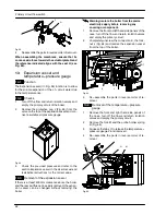
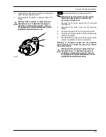
Fig. 62
4
Reassemble the parts in reverse order of removal.
When assembling the membrane, ensure that its
concave side faces towards the actuator plate
G
and
the reference indicated aligns with the seat
H
(see
Fig. 62).
13
Expansion vessel and
temperature---pressure gauge
13.1
Function
The Expansion vessel (
I
in Fig. 58) function is to allow
for the volume expansion of the c.h. circuit water due
to the temperature rise.
13.2
Checks
1
Turn off the flow and return isolation valves and
empty the primary circuit of the boiler.
2
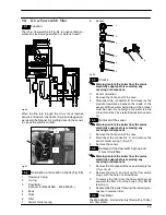
Remove the protective cap
J
(Fig. 63) from the
valve on the top of the expansion vessel and con-
nect a suitable air pressure gauge.
J
Fig. 63
3
Check the pre---load pressure and refer to the
section
Expansion vessel
in the
User manual and
installation instructions
for the correct value.
13.3
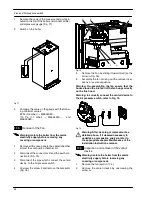
Removal of the expansion vessel
If there is at least 400 mm clearance above the boiler
and the rear exit flue can be easily removed, the expan-
sion vessel can be changed without removing the
boiler.
Warning: isolate the boiler from the mains
electricity supply before removing any
covering or component.
1
Remove the front and left hand side panels of the
case, turn off the flow and return isolation valves
and empty the primary circuit.
2
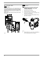
Completely unscrew the connection
K
, the lock-
nut
L
(Fig. 64) and remove the expansion vessel
from the top of the boiler.
B
NO T
L
K
Fig. 64
3
Re---assemble the parts in reverse order of re-
moval.
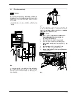
13.4
Removal of the temperature---pressure
gauge
1
Remove the front and right hand side panels of
the case, turn off the flow and return isolation
valves and empty the primary circuit.
2
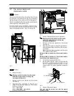
Remove the fork
M
and the probe holder spring
N
(Fig. 65).
3
Squeeze the tabs
O
to release the temperature---
pressure gauge
P
and remove it.
4
Re---assemble the parts in reverse order of re-
moval.
P
M
N
O
Fig. 65


