- 79 -
MAINTENANCE
MAINTENANCE
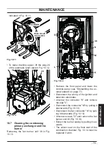
indicated in Fig. 10.11.
Fig. 10.11
OPEN
CLOSED
Main circuit
drain valve
9
•
To make draining easier, lift the plug 24
of the automatic relief valve in Fig. 10.12.
Fig. 10.12
24
10.7 Cleaning the condensing
primary exchanger and the
burner
Removing the fan burner unit 38 in Fig.
10.13.
Fig. 10.13
K
L
38
M
N
O
•
Remove the front panel and lower the
controls panel (see "Dismantling the ex
-
ternal panels" on page 77).
•
Disconnect the wiring of the ignition and
detection electrodes.
•
Unscrew the connector "K" and remove
the pipe "L".
•
Disconnect the connector "M" by pulling it
downwards (Fig. 10.13).
•
Disconnect the fan connector "N" by pull
-
ing it downwards (Fig. 10.13).
•
Unscrew screws "O" and remove the fan
burner unit 38 (Fig. 10.13).
•
Extract the burner casing by pulling it out
-
wards.
•
The silicon seal on the front wall of the
combustion chamber Fig. 10.14 must be
replaced if worn.


