


- 55 -
INST
ALLA
TION
INSTALLATION
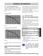
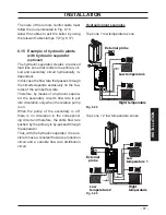
Fig. 6.12
90°=---1 m
45°=---0,5 m
90°=---0,85 m
45°=---0,65 m
ø 60 mm
ø 60/100 mm
In the last section, the fumes are expelled
through a vertical section.
Extensions and elbows can be added to ex-
tend the kit’s length.
Maximum equivalent length “
a+b
” (Fig.
6.12) of 15 metres can be achieved utilising
extensions.
Each additional elbow reduces the overall
acceptable length of the flue system as fol-
lows:
45° (60/100 mm) reduce length by 0,5 m.
90° (60/100 mm) reduce length by 1 m.
45° (60 mm) reduce length by 0,65 m.
90° (60 mm) reduce length by 0,85 m.
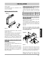
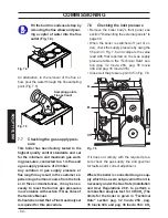
6.9 Electric connection
• Unscrew screws "V"
and remove the front
panel "W" by pulling it and pushing it to-
wards the top so that it is freed from the
top housing Fig. 6.13.
Fig. 6.13
V
W
• Identify the terminal block cover lid "X"
(Fig. 6.14) and open it.
Содержание Inovia 25C
Страница 90: ...90 NOTES...
Страница 91: ......