- 29 -
INST
ALLA
TION
TECHNICAL INFORMATION
4
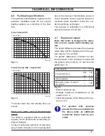
4.1 Overview
Fig. 4.1
21
22
49
46
39
43
31
27
38
32
34
35
26
45
41
30
33
40
47
25
44
42
29
48
36
37
52
28
53
Страница 1: ...Wall hung fanflue roomsealed high efficiency gas boiler User manual and Installation instructions Inovia Models G C Appl No Inovia 25C 47 583 32 Inovia 30C 47 583 33 Inovia 35C 47 583 34...
Страница 2: ...stems in the UK and to encourage regular servicing to optimise safety efficiency and performance Benchmark is managed and promoted by the Heating and Hot water Industry Council For more information vi...
Страница 3: ...iate Building Regulations England and Wales All installations must be notified to Local Area Building Control either directly or through a Competent Persons Scheme A Building Regulations Compliance Ce...
Страница 4: ...system com patible with its performance and output can be used only for those purposes for which it has been specially designed must not be touched by children or by those unfamiliar with its operatio...
Страница 5: ...ot extinguish with water Precautions Do not incinerate Avoid contact with broken leaking phials Do not purposely puncture First aid medical attention must be sought following eyes skin contact wash wi...
Страница 6: ...h cold and hot to the British Standard BS 7593 2006 Code of practice in order to remove system and installation debris It is also sensible to initially fire and commission the boiler before connecting...
Страница 7: ...and the external probe 60 6 14 Remote electric connection optional 60 6 15 Example of hydraulic plants with hydraulic separator 61 7 COMMISSIONING 62 7 1 Warnings 62 7 2 Electrical installation 62 7...
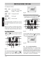
Страница 8: ...right side Fig 1 1 1 1 Controls panel 1 2 Isolation valves Fig 1 2 2 3 4 5 6 7 8 9 10 2 Gas supply label 3 C h flow valve 4 D h w outlet valve 5 Gas inlet valve 6 D c w inlet valve 7 C h return valve...
Страница 9: ...the timer 3 star preheating function and heating flow timer 20 LCD display RESET that takes all parameters back to the factory value occurs only by setting parameter 08 04 Reset is displayed by switc...
Страница 10: ...wer delayed by inhibi tor AFCT or other events INFO menu input enabled Indicate the status of the scheduling re quest Flashing comfort program in process reduced pro gram in process The day of the wee...
Страница 11: ...ck lighting has to be flashing Constantly illuminat ed set value Constantly illumi nated temperature is displayed without decimals but with a sign probe con nected Indicated boiler pressure Constantly...
Страница 12: ...uring D h w op eration Boiler Stand By hy phens are turned on in sequence to simulate running antifreeze pro tection activated LCD FUNCTION In the case of incorrect pressure the value is visualised wi...
Страница 13: ...Boiler in chimney sweep in function The activation of the chimney sweep occurs configuring the param eter P09 01 and is visualized LP minimum d h w hP minimum heating cP maximum heating dP maximum d h...
Страница 14: ...w supply checking that the pressure in dicated on the bottom part of the display Fig 2 2 In the case of incorrect pressure the value is visualised with a flashing symbol Fig 2 2 high pressure 2 8 bar...
Страница 15: ...e required pressure 2 3 Ignition Check that the valves located in the lower part of the boiler are open Fig 2 3 Fig 2 3 Open position Turn on the electricity supply to the boiler switching on the fuse...
Страница 16: ...12 13 14 15 16 17 18 19 The LCD display displays the boiler tempera ture primary circuit and the and symbols the symbol slowly flashes Fig 2 8 Fig 2 8 Hot water production functioning only Press the...
Страница 17: ...stalled When the external temp probe optional is installed your boiler automatically adjusts the temperature of the c h system water flow in relation to the external temperature In this case the boile...
Страница 18: ...15 16 17 18 19 Press keys 11 or 12 Fig 2 14 to select the in dividual day 1 2 3 4 5 6 7 or if you want groups of days with the same time bracket scheduling hold down key 11 until groups 1 5 1 6 1 7 6...
Страница 19: ...d or they over write them fully or partly To reset all the time brackets please refer to paragraph 1 3 to page 9 Timed manual heating function When using this function it is possible to tem porarily e...
Страница 20: ...19 briefly to save the values en tered and upon leaving the menu the display will indicate OK to confirm Fig 2 23 Fig 2 23 To exit programming without making any mod ifications press keys 17 and 18 F...
Страница 21: ...led by the Authorised Service Engineer D h w request When the boiler has a power request in the d h w mode the symbol is displayed on the display followed by an increase of the heating water flow temp...
Страница 22: ...28 Fig 2 28 Fig 2 29 11 12 13 14 15 16 17 18 19 Press key 11 or 12 to select the 4 programmes P1 P4 with the related on and off times P1 on P1 off P4 on P4 off with minimum intervals of 15 minutes Fig...
Страница 23: ...l appears on the display Fig 2 34 Fig 2 33 11 12 13 14 15 16 17 18 19 Fig 2 34 If a long period of inactivity is envisioned Switch off the electricity supply to the boiler by means of the fused spur i...
Страница 24: ...2 Therefore when the boiler is not lit and used in cold weather with consequent risk of freezing do not switch off the boiler at the fused spur isolation switch or close the gas inlet cock If the boi...
Страница 25: ...d a code that precedes the letter E and the writing RESET see LCD general features to page 10 appear on the LCD display it in dicates that the safety lock out has stopped the boiler The display backgr...
Страница 26: ...the pressure relief valve Check on the pressure gauge that the pres sure in the central heating circuit is not close to 3 bars In this case temperature rise in the circuit can cause the pressure relie...
Страница 27: ...J01 value K curve value configured in loco J02 value Offset climatic curve value J03 value Calculated heating set point with climatic curve or set configured J04 value Temperature NTC delivery J05 va...
Страница 28: ...e NTC E07 Faulty external temp probe NTC with K set E08 Flame detection error E11 Lack of circulation T 105 C E14 3 9 Flue probe The flue probe 22 and safety thermal fuse 28 indicated in Fig 3 8 are a...
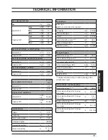
Страница 29: ...29 INSTALLATION TECHNICAL INFORMATION 4 TECHNICAL INFORMATION 4 1 Overview Fig 4 1 21 22 49 46 39 43 31 27 38 32 34 35 26 45 41 30 33 40 47 25 44 42 29 48 36 37 52 28 53...
Страница 30: ...t exchanger air purger valve 22 Flue temperature probe NTC 23 C h temperature probe NTC delivery 24 C h temperature probe NTC return 25 Condensing heat exchanger 26 Safety thermostat 27 Flame detectin...
Страница 31: ...supply terminal block external controls terminal block 39 Primary circuit pressure switch 40 Condensate trap 41 D h w heat exchanger 42 Three way diverter valve 43 Three way electric actuator valve 4...
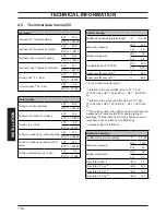
Страница 32: ...flow temperature settings C 25 85 Maximum pressure kPa 250 bar 2 5 Minimum pressure kPa 30 bar 0 3 Available head in 1000 l h kPa 23 0 bar 0 230 Seasonal efficency G20 c 88 7 Seasonal efficency G31 c...
Страница 33: ...ee IPX5D External fuse rating A 3 Internal fuse rating A N 2 2 AF Flue design Boiler type B23P C13 C33 C43 C53 C63 C83 Coaxial mm 60 100 Twin split pipes mm 80 80 Roof mm 80 125 Nominal heat flow rate...
Страница 34: ...CO2 content with gas G20 range min max 9 3 9 9 CO2 content with gas G31 range min max 10 0 10 9 Minimum heat input A E kW 5 9 CO2 content with gas G20 range min max 8 7 9 3 CO2 content with gas G31 r...
Страница 35: ...flow temperature settings C 25 85 Maximum pressure kPa 250 bar 2 5 Minimum pressure kPa 30 bar 0 3 Available head in 1000 l h kPa 27 0 bar 0 270 Seasonal efficency G20 c 88 7 Seasonal efficency G31 c...
Страница 36: ...5D External fuse rating A 3 Internal fuse rating A N 2 2 AF Flue design Boiler type B23P C13 C33 C43 C53 C63 C83 Coaxial mm 60 100 Twin split pipes mm 80 80 Roof mm 80 125 Nominal heat flow rate A E k...
Страница 37: ...CO2 content with gas G20 range min max 9 2 9 8 CO2 content with gas G31 range min max 9 9 10 8 Minimum heat input A E kW 8 3 CO2 content with gas G20 range min max 8 7 9 3 CO2 content with gas G31 ra...
Страница 38: ...Max flow temperature settings C 25 85 Maximum pressure kPa 250 bar 2 5 Minimum pressure kPa 30 bar 0 3 Available head in 1000 l h kPa 27 0 bar 0 270 Seasonal efficency G20 c 88 6 Seasonal efficency G3...
Страница 39: ...D External fuse rating A 3 Internal fuse rating A N 2 2 AF Flue design Boiler type B23P C13 C33 C43 C53 C63 C83 Coaxial mm 60 100 Twin split pipes mm 80 80 Roof mm 80 125 Nominal heat flow rate A E kW...
Страница 40: ...CO2 content with gas G20 range min max 9 3 9 9 CO2 content with gas G31 range min max 10 0 10 9 Minimum heat input A E kW 8 3 CO2 content with gas G20 range min max 8 7 9 3 CO2 content with gas G31 r...
Страница 41: ...irculation in the heating plant due to the closing of thermostatic valves or circuit elements valves by pass ensures a minimum water circulation inside the con densing primary exchanger The by pass is...
Страница 42: ...iler and system For Ireland IE it is necessary to com plete a Declaration of Conformity to indicate compliance to I S 813 2002 This appliance must be installed by a competent person in accordance with...
Страница 43: ...ace as an outhouse or lean to It is important that the position of the terminal allows a free passage of air across at all times The terminal should be located with due regard for the damage or discol...
Страница 44: ...d be fitted in accord ance with BS 6891 and the complete instal lation should be tested for tightness For Ireland IE refer to I S 813 2002 5 5 Air supply The room in which the boiler is installed does...
Страница 45: ...1 2003 BSEN 14446 2004 the following notes are given for general guidance For Ireland IE refer to I S 813 2002 Pipework Copper tubing to BSEN 1057 is recom mended for water pipes Jointing should be ei...
Страница 46: ...10 bar Where it is likely that the mains domestic water pressure may exceed 5 bar it is possible due to internal water hammer effects that the pressure within the domestic system can increase to a le...
Страница 47: ...of the local water company 5 11 Electrical supply Warning this appliance must be earthed External wiring to the appliance must be carried out by a competent person and be in accordance with the curre...
Страница 48: ...ments of the distribu tors and comply with current Regulations and laws in force The safety relief valve and the condensate drain must be connected to a suitable drain or discharge in a safe manner Th...
Страница 49: ...product in the circulating water The latter option in particular not only cleans out the system but also has an anti corrosive effect by promoting formation of a protective skin on metal surfaces and...
Страница 50: ...ensate drain 25 plastic sizes in mm o d Condensate drain to be realised with min pipe 30 mm 6 6 Mounting the boiler Assemble the pre piping kit bracket by screwing the four screws L Fig 6 3 Fix the wa...
Страница 51: ...Water circulation c h pag 45 in this manual 6 7 Fitting the flue system For a correct installation of the flue pipe re fer to the sheet provided together with the pre selected kit The horizontal route...
Страница 52: ...of flu The flue exhaust air intake can be installing in the mode C13 C33 C53 C63 Refer to the sheet provided with the pre selected kit in separate packaging The horizontal routes of the flue pipes mus...
Страница 53: ...ontal and however the terminal must always ex haust horizontally Additional bends at 45 or 90 Fig 6 8 C Coaxial bends 60 100 mm These bends when used with the pipe re duce the maximum length of the fl...
Страница 54: ...ue 25 kW 93 C 30 kW 98 C 35 kW 98 C Maximum recircula tion of CO2 in the suction duct 25 kW 0 95 30 kW 0 95 35 kW 0 95 Roof flue exhaust kit Fig 6 11 Coaxial pipe 80 125 mm with a nominal height of 0...
Страница 55: ...d utilising extensions Each additional elbow reduces the overall acceptable length of the flue system as fol lows 45 60 100 mm reduce length by 0 5 m 90 60 100 mm reduce length by 1 m 45 60 mm reduce...
Страница 56: ...minals to which the room thermostat must be connected Connect the earth cable yellow green to an effective earth plant The earth cable must be the longest of the electric power supply cables The appli...
Страница 57: ...3 when connecting any type of ambient thermostat The electric cables of the ambient thermo stat are inserted between clamps 1 and 3 as in Fig 6 18 or Fig 6 19 or Fig 6 20 Be careful not to connect pow...
Страница 58: ...s Y Fig 6 17 Connection of a remote controlled zone valve Connecting a zone valve to the terminal of the auxiliary card and the remote control to the specific terminals it is possible to control this...
Страница 59: ...ard terminal board Zone valve To remotely connect utilise the terminals in dicated in Fig 6 27 6 11 External frost protection Connect the frost thermostat between ter minals 1 and 2 as shown in Fig 6...
Страница 60: ...different channels to the voltage ones 230 V since they are powered at a safe ty low voltage and their maximum length must not exceed 20 meters Use the clamps indicated in Fig 6 27 to connect the ext...
Страница 61: ...mps flow rate Therefore by means of a hydraulic separa tor the secondary circuit s flow rate is put into circulation only when the relative pump is on When the pump of the secondary is off there is no...
Страница 62: ...be carried out by a competent person i e polarity earth continu ity resistance to earth and short circuit If a fault has occurred on the appliance the fault finding procedure should be followed as spe...
Страница 63: ...ove any loose particles and any system debris before start ing the boiler for the first time The flushing procedure must be in line with BS7593 2006 Treatment of Water in d h w c h Systems When the in...
Страница 64: ...ce Manual It should be noted that a Flue Gas Analyser is required for this procedure 7 8 Checking the inlet pressure Remove the boiler body s front panel see section Dismantling the external panels to...
Страница 65: ...the double pole isolation switch The LCD will display the symbol Fig 7 7 Fig 7 7 Press the 14 key for 2 seconds until both and symbols appear on the dis play Fig 7 8 Fig 7 8 11 12 13 14 15 16 17 18 1...
Страница 66: ...eset button is inhibited To restore its func tion it is necessary to switch the boiler off and on from the electrical mains using the fused spur isolation switch fitted adjacent to the ap pliance 7 10...
Страница 67: ...remote control Fig 7 16 External temperature C 20 20 15 10 5 0 5 10 15 20 25 30 40 50 60 70 80 C h flow temperature C K 6 K 4 K 3 K 2 K 1 5 K 1 K 0 5 The K coefficients is a parameter that increas es...
Страница 68: ...writing P15 SEt alternates on the dis play Fig 7 20 Fig 7 20 By pressing key 14 Fig 7 17 confirmation of the inserted value is obtained Press keys 17 or 18 Fig 7 17 to exit with out changing the valu...
Страница 69: ...s button to exit from mode Fig 7 23 7 12 Setting the pump speed The pump management parameter P03 is factory set to automatic 02 In other words at the maximum speed in normal operation and at the aver...
Страница 70: ...on of about one minute at the end of each heat request This time can be changed by a minimum of zero to a maximum of four minutes by acting on programming both from the panel controls and the remote c...
Страница 71: ...minutes or by cutting power Programming using the REMOTE control Press button for more than 3 seconds to enter in mode Fig 7 32 Fig 7 32 0 2 1 8 1 21 15 6 3 9 Press buttons and at the same time to en...
Страница 72: ...ing keys 17 or 18 until the letters P10 are displayed on the LCD display indicating that parameter 10 Fig 7 38 has been activated Fig 7 38 It is possible to modify parameter 10 by 00 0s to 100 510s us...
Страница 73: ...or decreased corre sponds to 2 seconds To modify the programmed SET act on but tons or and wait for the number programmed to flash Fig 7 43 Fig 7 43 To exit programming press button 7 15 Checking the...
Страница 74: ...ntrols this will ensure the greatest possible fuel economy Explain the function and use of the function selector Explain and demonstrate the function of time and temperature controls if fitted Explain...
Страница 75: ...central heating requirement By pressing key 14 Fig 7 47 confirmation of the inserted value is obtained Press keys 17 or 18 Fig 7 47 to exit with out changing the value Exiting the programming mode is...
Страница 76: ...for 10 seconds at the same time until the letters P01 are displayed on the LCD display and the value of the parameter 35 Inovia 25C 36 Inovia 30C or 37 Inovia 35C indicating that pa rameter 01 Fig 7...
Страница 77: ...fixing fork A and remove the pipe B Fig 8 1 Fig 8 1 A B C Carry out gas conversion by correctly re placing the gas restrictor Fig 8 2 refer ring to the Technical Data section pag 32 Inovia 25C pag 35...
Страница 78: ...05 G31 By pressing key 14 Fig 8 3 confirmation of the inserted value is obtained Press keys 17 or 18 Fig 8 3 to exit with out changing the value Exiting the programming mode is au tomatic after 15 min...
Страница 79: ...ing maintenance opening or dismantling boiler panels The En gineer should complete the Service Interval Record at the back of the manual 9 2 Programming the maintenance period Activate the clock funct...
Страница 80: ...e The remaining months until maintenance will be replicated in read only in the info section under value J15 N B The flashing symbol in Fig 9 5 is not an error The boiler continues to run normally but...
Страница 81: ...Fit the front panel D hooking it on the up per side Push the spring towards the internal side of the boiler and simultaneously push the front case panel D until it is completely hold in place Fig 9 8...
Страница 82: ...Cleaning the condensing prima ry exchanger and the burner Removing the fan burner unit 47 in Fig 9 12 Fig 9 12 J K L 47 M N O P Q Remove the body s front panel and turn the controls panel see Dismantl...
Страница 83: ...dical servicing or dis turbance the combustion chamber silicon seal Fig 9 13 must be fully inspected and replaced at the discretion of the service engineer After any disturbance to the chamber door se...
Страница 84: ...Inovia 25C Nominal heat input A E kW 20 0 Nominal efficency 97 4 Combustion efficency 97 6 Air index n 1 23 Flue gas CO2 content 9 2 9 8 Flue gas O2 content 3 9 Flue gas CO content ppm 120 Flue gas t...
Страница 85: ...as tightness Recheck operational pressures as described in section Checking the gas supply pressure to page 64 of this manual 9 15 Water inhibitor concentration Where chemical products are used the le...
Страница 86: ...te between the heated water tempera ture i e 32 we are in the chimney sweep function at the minimum power during heat ing Fig 9 23 Fig 9 23 Chimney sweep function at maximum out put in heating mode Pr...
Страница 87: ...E at maximum output in domestic hot water mode Fig 9 25 Fig 9 25 Press keys 14 17 18 Fig 9 20 at the same time again to exit the chimney sweep mode and return to the previously set boiler status Fig 9...
Страница 88: ...ect the customer s statutory rights If yes and if required by the manufacturer has a water scale reducer been fitted Condensing Boilers only The condensate drain has been installed in accordance with...
Страница 89: ...er Name Company Name Telephone No Gas Safe Register No Comments Signature Date Engineer Name Company Name Telephone No Gas Safe Register No Comments Signature Date Engineer Name Company Name Telephone...
Страница 90: ...90 NOTES...
Страница 91: ......
Страница 92: ...Biasi UK Ltd Commercial Road Leamore Enterprise Park WALSALL WS2 7NQ Sales Tel 01922 714600 Tech Service Tel 01922 714636 www biasi co uk 1796221960 17962 2196 0 1512 92A5 UK 04 04 2012 N...