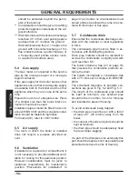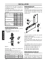
- 46 -
INST
ALLA
TION
INSTALLATION
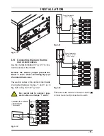
Connecting the zone valves controlled by
the ambient thermostat
Fig. 6.23
L
N
V
T
Zone valve
with micro contact
Ambient
Thermostat
Potential free contacts of the zone valve micro switch
Use the ambient thermostat's clamps indicat
-
ed in
Fig. 6.17
and
Fig. 6.18
to connect the
zone valve Insert the electric cables of the
zone valve's micro switch contacts in clamps
“1 and 3” of the ambient thermostat's terminal
block as in Fig. 6.18
.
Remove the electric jumper between “1
and 3”.
Be careful not to connect pow-
ered cables on clamps “1 and 3”.
The route of the boiler and ambient thermo
-
stat's electric power supply cable or wires
must follow the route indicated in Fig. 6.18
.
Allow the cables to exit the boiler by using the
relevant cable clamps S (Fig. 6.19).
6.11
External frost protection
•
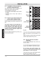
Connect the frost thermostat between termi
-
nals 1 and 2 as shown in Fig. 6.24
or
Fig.
6.25.
Do not connect live wires to terminals to
which the frost thermostat must be con-
nected.
Fig. 6.24
Room thermostat
N
L
3
2
1
(230V rating)
Frost Thermostat
(230V rating)
T
T
Fig. 6.25
1
2
3
L
N
Frost thermostat
(230V rating)
Room
thermostat
with anticipating
resistor
(230V rating)
T
T
6.12 Connecting a system boiler to a
cylinder
Two schematic wiring diagrams are given in
this section showing two possible ways to
connect an external programmer to a mid-
position diverter valve to provide independent
timed and thermostatic control of heating and
hot water.
Fig. 6.26
and
Fig. 6.27 are divided in two parts.


