


- 45 -
INST
ALLA
TION
INSTALLATION
Fig. 6.19
S
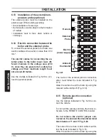
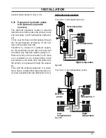
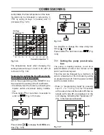
6.10 Connecting the room thermo-
stat or zone valves
Use the clamps indicated in Fig. 6.17
to con-
nect the ambient thermostat.
Remove the electric jumper present be-
tween “1 and 3” when connecting any type
of ambient thermostat.
The electric cables of the ambient thermostat
are inserted between clamps “1 and 3” as in
Fig. 6.20
or
Fig. 6.21
or
Fig. 6.22
.
Be careful not to connect pow-
ered cables on clamps “1 and 3”.
Fig. 6.20
1
T
Potential clean contacts
of the Ambient
Thermostat
Fig. 6.21
N
L
3
2
1
Room thermostat
(230V rating)
T
Fig. 6.22
Room thermostat
1
2
3
L
N
with delay resistor
(230V rating)
T
The thermostat must be insulation class II ( )
or must be correctly connected to earth.