- 54 -
INST
ALLA
TION
COMMISSIONING
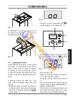
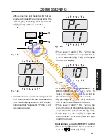
Switch off the boiler by pressing the
• 11
( Fig. 7.6 )key for 2 seconds until the
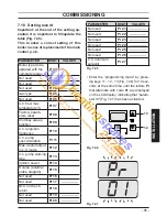
symbol appears on the LCD display ( Fig.
7.5 ).
The boiler will now go through an ignition
sequence and the burner will light.
If after four ignition attempts (about four
minutes) the boiler does not function and a
code that alternates between the letter
Er
and the writing
reset
appear on the LCD
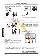
display, it indicates that the safety lock-out
has stopped the boiler. The display back-
ground fl ashes ( Fig. 7.8 ).
Fig. 7.8
RESET
RESET
Press the reset key on the boiler control
panel 11 ( Fig. 7.6 ) to reset its functioning.
For the fi rst lighting up and following main-
tenance procedures for the gas supply, it
may be necessary to repeat the resetting
operation several times so as to remove the
air present in the pipework.
After fi ve consecutive resetting attempts the
reset button is inhibited. To restore its func-
tion it is necessary to switch the boiler off
and on from the electrical mains, using the
fused spur isolation switch fi tted adjacent to
the appliance.
Checking the gas supply
7.7
pressure
This boiler has been factory tested to the
highest quality control standards and set
for the minimum and maximum gas work-
ing pressures, connected to a 1 m fl ue
and a gas supply pressure of 20 mbar.
Any variation in gas supply pressure or
fl ue length may result in the customer
experiencing a harmonic noise from the
boiler. In these circumstances, it may be
necessary to reset the burner gas pres-
sures in accordance with section 11 Gas
Valve of the Service Manual.
It should be noted that a Flue Gas Ana-
lyser is required for this procedure.
Checking the inlet pressure
7.8
Remove the boiler body's front panel, see
•
section "Dismantling the external panels"
to page 69
.
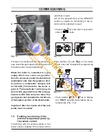
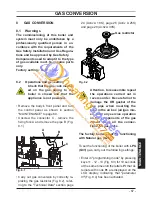
When the boiler is switched off (out of or-
•
der), check the supply pressure by using
the
26
point in
Fig. 7.9
and compare the
value read with that reported on the Gas
supply pressure table in the "Technical
Data" section ( pag. 24 Activ A 18S, pag.
26 Activ A 25S and pag. 28 Activ A 30S).
Close well the pressure point
• 26
in
Fig.
7.9
.


