- 33 -
INST
ALLA
TION
- 33 -
INST
ALLA
TION
GENERAL REQUIREMENTS
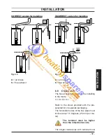
Fig. 5.3
Dimensions in mm
Connection of condensate drainage pipe
downstream of a sink waste trap
A
Condensate
drain
E
F
A
Boiler
E
Sink
F
Open end of condensate drainage pipe
direct into gully below grating but above
water level
Water circulation (c.h.)
5.8
Detailed recommendations are given in BS
6798 and BS 5449; the following notes are
given for general guidance.
For Ireland (IE), refer to I.S.813.2002.
Pipework
Copper tubing to BSEN 1057 is recom-
mended for water pipes. Jointing should be
either with capillary soldered or with com-
pression fi ttings.
Where possible pipes should have a gradi-
ent to ensure air is carried naturally to air
release points and water fl ows naturally to
drain taps.
The appliance has a built-in automatic air
release valve, it should be ensured as far as
possible that the appliance heat exchanger
is not a natural collecting point for air.
Except where providing useful heat, pipes
should be insulated to prevent heat loss and
to avoid freezing.
Particular attention should be paid to pipes
passing through ventilated spaces in roofs
and under fl oors.
By-pass
The appliance includes an automatic by-
pass valve which protects the main heat
exchanger in case of reduced or interrupted
water circulation through the heating system
due to the closing of thermostatic valves or
cock-type valves within the system.
The by-pass is calibrated to assure a mini-
mum fl ow of 200-300 lts/hr through the main
heat exchanger.
If you are installing a system that includes
thermostatic radiator valves (TRV) and/or
small bore (8-10 mm) it may be necessary
to fi t an external by-pass to facilitate correct
operation of the boiler.
The fi tting of an external bypass helps to
prevent and limit system noise.
Air release points
These must be fi tted a tall high points where
air will natural collect and must be sited to
facilitate complete fi lling of the system.
Expansion vessel
The appliance has an integral sealed expan-
sion vessel to accommodate the increase of
water volume when the system is heated.
Refer to Fig. 4.5 on page 23 for its techni-
cal data.
If the heating circuit has an unusually high
water content, calculate the total expansion
and add an additional sealed expansion
vessel with adequate capacity.
Mains water feed: central heating
There must be no direct connection to the
mains water supply even through a non re-


