


CH – PE – WT100
B-
N
OTE TECNICHE PER L
’
INSTALLAZIONE
/I
NSTRUCTIONS FOR THE ISTALLER
N
OTAS TÉCNICAS PARA LA INSTALACIÒN
/
Edition 07–2003
– 23 –
I
UK
E
P
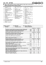
RESSIONE DI ALIMENTAZIONE GAS
/ G
AS SUPPLY PRESSURES
P
RESIÓN DE ALIMENTACIÓN DE GAS
25 WT100
32 WT100
Metano G20 / Natural gas G20 / Natural G20
Norm.
Pa
mbar
2000
20
Metano G20 / Natural gas G20 / Natural G20
Min.
Pa
mbar
1700
17
Metano G20 / Natural gas G20 / Natural G20
Max.
Pa
mbar
2500
25
Butano G30 / Butane G30 / Butano G30
Norm.
Pa
mbar
2900
29
Butano G30 / Butane G30 / Butano G30
Min.
Pa
mbar
2000
20
Butano G30 / Butane G30 / Butano G30
Max.
Pa
mbar
3500
35
Propano G31 / Propane G31 / Propano G31
Norm.
Pa
mbar
3700
37
Propano G31 / Propane G31 / Propano G31
Min.
Pa
mbar
2500
25
Propano G31 / Propane G31 / Propano G31
Max.
Pa
mbar
4500
45
U
GELLI
/ N
OZZLES
/ I
NYECTORES
Pilota/Pilot flame/llama piloto
25 WT100
32 WT100
Metano G20 / Natural gas G20 / Natural G20
0.45
mm/10
260
Butano G30 / Butane G30 / Butano G30
0.24
mm/10
155
Propano G31 / Propane G31 / Propano G31
0.24
mm/10
155
D
ATI ELETTRICI
/ E
LECTRICAL DATA
/ D
ATOS ELÉCTRICOS
25 WT100
32 WT100
Tensione / Voltage / Tensión
V~
220 - 240
Frequenza / Frequency / Frecuencia
Hz
50
Potenza elettrica / Electric power / Potencia eléctrica
W
80
Grado di protezione / Protection level / Grado de protección
IP20
P
ROGETTAZIONE CAMINO
/ F
LUE DESIGN
/ D
ISEÑO CHIMENEA
*
25 WT100
32 WT100
Portata termica nomimale / Nominal thermal capacity / Capacidad calorífica nominal
kW
27,9
34,8
Temperatura dei fumi / Flue gas temperature / Temperatura de los humos
°C
115
110
Portata massica fumi / Flue gas mass discharge / Capacidad de masa de los humos
kg/h
101,16
133,56
Portata massica aria / Air mass discharge / Capacidad de masa de aire
kg/h
99,36
131,04
* Valori riferiti alle prove con camino di 1 m / The values refer to tests with a 1 m flue
Valores correspondientes a las pruebas con chimenea de 1 m
A
LTRE CARATTERISTICHE
/ O
THER CHARACTERISTICS
/ O
TRAS CARACTERÍSTICAS
25 WT100
32 WT100
Altezza / Height / Alto
mm
1360
1360
Larghezza / Width / Ancho
mm
600
600
Profondità / Depth / Profundidad
mm
760
760
Peso / Weight / Peso
kg
185
200
Diametro condotto fumi / Flue diameter / Diámetro del conducto de humos
mm
130
150
G 20
Hi = 9,45 kWh/m
3
(15 °C, 1013,25 mbar) / G 20
p.c.i. 35,9 MJ/m
3
/ G 20
p.c.i. 35,9 MJ/m
3
G 30
Hi = 12,67 kWh/kg (15 °C, 1013,25 mbar) / G 30
p.c.i. 45,6 MJ/kg / G 30
p.c.i. 45,6 MJ/kg
G 31
Hi = 12,87 kWh/kg (15 °C, 1013,25 mbar) / G 31
p.c.i. 46,4 MJ/kg / G 31
p.c.i. 46,4 MJ/kg
–
1 mbar corrisponde a circa 10 mm H
2
O / 1 mbar corresponds to about 10mm H
2
O / 1 mbar corresponde a 10 mm H
2
O aproximadamente
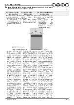
4.7 V
ASO D
’
ESPANSIONE
RISCALDAMENTO
4.7 C
ENTRAL HEATING
EXPANSION TANK
4.7 V
ASO DE EXPANSIÓN
CALEFACCIÓN
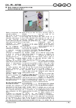
La differenza di altezza tra la
valvola di sicurezza ed il
punto più alto dell’impianto
può essere al massimo
7 metri.
Per differenze superiori,
aumentare la pressione di
precarica del vaso
d’espansione e dell’impianto a
freddo di 0,1 bar per ogni
aumento di 1 metro.
The difference in height
between the safety valve and
the highest point of the
system can be up to a
maximum of 7 metres.
For greater differences,
increase the expansion tank’s
preload pressure and the cold
system by 0.1 bar for each 1
metre increase.
La diferencia de altura entre
la válvula de seguridad y el
punto más alto de la
instalación puede ser de 7
metros como máximo.
Para diferencias superiores,
aumentar la presión de
precarga del vaso de
expansión y de la instalación
en frío 0,1 bar por cada
aumento de 1 metro.
Capacità totale / Total capacity / Capacidad total
l
8,0
Pressione di precarica / Preload pressure / Presión de precarga
kPa
bar
100
1,0
Capacità utile / Useful capacity / Capacidad útil
l
4,3
Contenuto massimo d’acqua nell’impianto
*
/ Maximum content of water in the system
*
Contenido máximo de agua en la instalación
*
l
150
Содержание 25 CH
Страница 2: ......