Biasi 25 CH Скачать руководство пользователя страница 10

CH – PE – WT100

A- 

N

OTE D

IMPIEGO 

/ U

SER INSTRUCTIONS


I

NSTRUCCIONES DE USO 

/

Edition 07–2003

– 6 –

I

UK

E

2.2 A

CCENSIONE

2.2 I

GNITION

2.2 E

NCENDIDO

1  Verificare che i rubinetti del

circuito riscaldamento del
gas e del circuito sanitario
(solo modello misto) siano
aperti.

2 Alimentare  elettricamente

la caldaia  azionando
l’interruttore bipolare
previsto nella installazione.

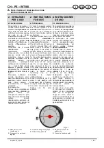
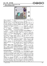
3 Verificare sul manometro

circuito riscaldamento se la
pressione dell’acqua é
regolare come indicato in
fig. 2.1

Se il manometro indica valori
prossimi allo zero riempire il
circuito agendo sul rubinetto
di carico e richiudendolo a
riempimento completato (il
valore di pressione dovrà
essere compreso tra 1 e 1,5
bar).

Non avviate mai la caldaia
senza la presenza di acqua
nel circuito di
riscaldamento.

4 Premere il pulsante di

caldaia accesa (3).

Solo per caldaie miste

5  Se si desidera utilizzare la

caldaia in riscaldamento,
premere il pulsante di
funzionamento inverno (9).

6  Se si desidera utilizzare la

caldaia solamente per la
produzione dell’acqua
calda sanitaria, premere il
pulsante di funzionamento
estate/inverno (9).

1 Check that the cocks on

the gas central heating
circuit and on the domestic
water circuit (only
combined models) are
open.

2 Turn the boiler on by

switching on the multi-way
switch fitted to the
appliance.

3 Check on the central

heating circuit gauge
whether water pressure is
regular, as indicated in fig.
2.1

If the values shown on the
gauge are near zero, fill the
circuit up by opening the fill-
up cock, closing it after the
circuit is full (pressure should
be between 1 and 1.5 bar).

Never turn the boiler on if
there is no water in the
central heating circuit.

4 Press the boiler on push

button (3).

Only for combined boilers

5  If you wish to use the boiler

for central heating, press
the winter functioning
mode push button (9).

6  If you wish to use the boiler

solely for the production of
domestic hot water, press
the summer/winter
functioning mode push
button (9).

1  Comprobar que los grifos

de gas del circuito de
calefacción y los del
circuito de agua sanitaria
(sólo modelos mixtos)
están abiertos.

2  Suministrar fluido eléctrico

a la caldera accionando el
interruptor bipolar
dispuesto en la instalación.

3  Averiguar en el manómetro

del circuito de calefacción
si la presión de agua es
regular según lo indicado
en la  fig. 2.1

Si el manómetro indica unos
valores próximos a cero llenar
el circuito actuando sobre el
grifo de llenado, cerrándolo
una vez finalizado el llenado
(el valor de presión debe ser
entre 1 y 1,5 bar).

No poner en marcha la
caldera sin agua en el
circuito de calefacción.

4  Pulsar el botón de caldera

encendida (3).

Sólo para las calderas
mixtas

5 Si se quiere utilizar la

caldera para calefacción,
pulsar el botón de
funcionamiento en invierno
(9).

6 Si se quiere utilizar la

caldera únicamente para la
producción de agua
caliente sanitaria,
presionar el botón de
funcionamiento en
invierno/verano (9).

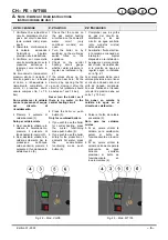
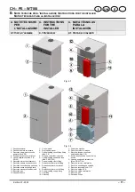
Fig. 2.2 – Mod. CH-PE

Fig. 2.3 – Mod. WT100

Содержание 25 CH

Страница 1: ...FIRED FOR HEATING AND DOMESTIC HOT WATER B100 CALDERAS EN FUNDICION DE GAS PARA CALEFFACION YPRODUCCION DE AGUA CALIENTE SANITARIA B100 Edition 07 2003 MANUALE TECNICO TECHNICAL MANUAL MANUAL T CNICO...

Страница 2: ......

Страница 3: ...g electrical household appliances The manufacturer in his continuous search to improve his products reserves the right to modify the data given herein without prior notice This documentation is for in...

Страница 4: ...a central heating system and or a hot water supply system compatible with its performance and output can be used only for those purposes for which it has been specially designed must not be touched by...

Страница 5: ...Funcionamiento imperfecto 3 3 4 5 6 7 8 9 10 10 11 11 12 12 13 B NOTE TECNICHE PER L INSTALLAZIONE B INSTRUCTIONS FOR THE INSTALLER B NOTA T CNICAS PARA LA INSTALACI N 4 NOTE TECNICHE PER L INSTALLAZ...

Страница 6: ...ON 9 1 Warnings 9 2 Operation 10 MAINTENANCE 10 1 Warnings 10 2 Disassembling casing panel 10 3 Draining off the central heating circuit 10 4 Emptying the D H W storage heater 10 5 Checking pressure i...

Страница 7: ...ometro bollitore sanitario 12 Pulsante ripristino dispositivo controllo fumi LEGENDA 1 Control panel 2 Casing front panel 3 Main switch 4 Reset button 5 Stop signal light 6 Safety thermostat reset but...

Страница 8: ...ata continuo T 35 K 9 l min Continuous capacity T 35 K 9 l min Caudal continuo T 35 K 9 l min 9 l min Tempo max ripristino 12 min Max reheating time 12 min Tiempo m x de r12establecimiento 12 min 12 m...

Страница 9: ...be used to produce domestic hot water making sure that the pressure shown on the gauge installed for the central heating system on models CH which is visible when you open the front panel of the casin...

Страница 10: ...r as indicated in fig 2 1 If the values shown on the gauge are near zero fill the circuit up by opening the fill up cock closing it after the circuit is full pressure should be between 1 and 1 5 bar N...

Страница 11: ...ng temperature of the centra heating water according to the outside temperature positioning the knob as follows La temperatura de alimentaci n del agua de calefacci n se puede regular desde un m nimo...

Страница 12: ...ble to adjust the hot water temperature to a level commensurate with the demand minimising the need to mix with water In addition if the water is particularly calcareous you can minimize the bother of...

Страница 13: ...h button 3 When you do not expect to use the boiler for a long period 1 Switch off the electricity supply to the boiler by means of the multi way switch fitted with the appliance 2 turn the gas supply...

Страница 14: ...has connected the pressure relief valve outlet to a drain pipe The manufacturers are not responsible for damage caused by opening of the pressure relief valve and consequent leakage of water if not co...

Страница 15: ...o funzionamento del sistema di evacuazione dei fumi camino o canna fumaria In questi casi consigliabile rivolgersi al Centro di Assistenza Autorizzato E vietato e pericoloso disinserire il dispositivo...

Страница 16: ...aia Questo controllo potr avvenire nel quadro di un contratto di manutenzione In particolare si consiglia di far procedere ai seguenti controlli il corpo caldaia il bollitore sanitario solo miste bruc...

Страница 17: ...ctuado el dispositivo de seguridad Para restablecer el funcionamiento de la caldera es necesario apretar el propio indicador que sirve tambi n de bot n de reposici n 4 Fig 3 3 Alla prima accensione ed...

Страница 18: ...e to air bubbles are heard during operation it is necessary to check on the gauge at regular intervals the pressure in the central heating circuit and fill up correctly if required For the CH models d...

Страница 19: ...er If noise is heard during functioning due to air bubbles It is the user s reponsibility to regularly check pressure in the central heating circuit If you find you have to add water too frequently ca...

Страница 20: ...usted to avoid the increase of the pressure over 8 bar which is the pressure value of the safety valve Moreover we recommend to install an expansion vessel of about 4 l capacity to avoid the increase...

Страница 21: ...ria 10 Raccordo mandata riscaldamento 11 Raccordo gas 12 Cappa antivento 1 Control panel 2 Front casing panel 3 Central heating circuit fill up fitting Mod PE 4 Flue gas control device probe 5 Central...

Страница 22: ...19 20 21 23 24 25 27 Windshield hood Flue gas control device probe Central heating supply fitting Central heating return fitting Gas fitting Manual bleed cock Gas valve inlet pressure tap Gas pressure...

Страница 23: ...ircuit fill up fitting Mod PE Central heating return fitting Gas fitting Expansion tank Mod PE Manual bleed cock 3 bar safety valve Mod PE Automatic bleed valve Mod PE Circulator Mod PE Gas valve inle...

Страница 24: ...tural G20 Max Pa mbar 2500 25 Butano G30 Butane G30 Butano G30 Norm Pa mbar 2900 29 Butano G30 Butane G30 Butano G30 Min Pa mbar 2000 20 Butano G30 Butane G30 Butano G30 Max Pa mbar 3500 35 Propano G3...

Страница 25: ...hot water inlet fitting Domestic hot water circulation fitting Domestic hot water outlet fitting Central heating supply fitting Gas fitting Windshield hood 3 bar safety valve Automatic bleed valve Cen...

Страница 26: ...0 TECHNICAL DATA 4 6 CARACTER STICAS T CNICAS WT100 25 WT100 32 WT100 Portata termica nominale Nominal thermal capacity Capacidad calor fica nominal kW 27 9 34 8 Portata termica minima Minimum thermal...

Страница 27: ...m flue Valores correspondientes a las pruebas con chimenea de 1 m ALTRE CARATTERISTICHE OTHER CHARACTERISTICS OTRAS CARACTER STICAS 25 WT100 32 WT100 Altezza Height Alto mm 1360 1360 Larghezza Width...

Страница 28: ...a 150 l es necesario disponer un vaso de expansi n adicional 4 8 VASO D ESPANSIONE SANITARIO 4 8 D H W EXPANSION TANK 4 8 VASO DE EXPANSI N AGUA SANITARIA Il vaso di espansione sanitario permette l es...

Страница 29: ...limenta quando la caldaia funziona in sanitario Con il selettore in pos estate il circolatore riscaldamento sempre disalimentato An electric command is sent to the ignition device each time a request...

Страница 30: ...he water drops below that set on the storage heater temperature adjustment in this condition the storage heater thermostat feeds the storage heater circulator that makes the water of the boiler body c...

Страница 31: ...be installed near the flue gas evacuation duct and the room must be equipped with a standard air intake for ventilating In the case of oil gas installation must also comply with the distributing compa...

Страница 32: ...dell acqua in esso circolante Quest ultima soluzione in particolare oltre a ripulire l impianto esegue The boiler must never be sealed inside a cupboard or niche it must always be possible for air to...

Страница 33: ...l raccordo del bollitore The measurements and data useful for installation of the boiler are given in sections 6 4 of this chapter 1 Install stop cocks on both the central heating water and gas circui...

Страница 34: ...CHE PER L INSTALLAZIONE INSTRUCTIONS FOR THE ISTALLER NOTAS T CNICAS PARA LA INSTALACI N Edition 07 2003 30 I UK E 6 4 DIMENSIONI E RACCORDI 6 4 DIMENSIONS AND FITTINGS 6 4 DIMENSIONES Y EMPALMES CH P...

Страница 35: ...i che il cavo di massa sia pi lungo della linea e del neutro in modo che in caso di strappo sia l ultimo ad essere scollegato Assicurarsi inoltre del corretto collegamento linea neutro all alimentazio...

Страница 36: ...CNICHE PER L INSTALLAZIONE INSTRUCTIONS FOR THE ISTALLER NOTAS T CNICAS PARA LA INSTALACI N Edition 07 2003 32 I UK E CALDAIA CH PE SCHEMI ELETTRICI CH PE BOILER ELECTRICAL WIRING CALDERA CH PE ESCHEM...

Страница 37: ...mo Spia di blocco Elettrodo di accensione Elettrodo di rilevazione Bruciatore pilota Accensione elettronica IG OP TA C TR TS TF PR SB EA ER BP AE LEGENDA Main switch Timer opz Room thermostat CH pump...

Страница 38: ...CNICHE PER L INSTALLAZIONE INSTRUCTIONS FOR THE ISTALLER NOTAS T CNICAS PARA LA INSTALACI N Edition 07 2003 34 I UK E CALDAIA WT100 SCHEMI ELETTRICI WT100 BOILER ELECTRICAL WIRING CALDERA WT100 ESCHEM...

Страница 39: ...nsione Elettrodo di rilevazione Bruciatore pilota Accensione elettronica IG EI OP TA Pr Pb TR TS TF TB TL PR SB R EA ER BP AE LEGENDA Main switch Summer winter swicth Timer opz Room thermostat CH pump...

Страница 40: ...ema con tres bombas de circulaci n CH PE Fig 6 6B P Circolatore R Rel T Termostato ambiente P Circulator R Relay T Room thermostat P Bomba de circulati n R Rel T Termostato de ambiente La P1 predispos...

Страница 41: ...ect the boiler s central heating circulator 5 and 6 Desconectar el ctricamente la bomba de circulaci n para calefacci n de la caldera desconectando los hilos de los bornes 5 y 6 6 7 SCHEMA ELETTRICO P...

Страница 42: ...pter that the electrical power water and gas characteristics comply with those on the rating plate that the burner is calibrated as prescribed by the manufacturer that the flow of air in the room unne...

Страница 43: ...a con una soluci n de agua jabonosa o un producto similar 3 Cerrar el grifo de gas de la caldera LLENADO DE LOS CIRCUITOS HIDRAULICOS 4 Abrir los grifos de la caldera dejando cerrado el grifo de gas 5...

Страница 44: ...r pump loosening the cap B in fig 7 1 If the circulator needs to be unjammed remove the cap completely and turn the rotor in the direction of the arrow on the plate 14 Reclose the circulator 15 Fill u...

Страница 45: ...servare il libretto note d impiego integro e a portata di mano per la consultazione 21 Check the boiler is working properly 22 Check pressures and gas flows as illustrated in the gas regulation checks...

Страница 46: ...presa di pressione E 4 Posizionare la regolazione di temperatura riscaldamento B in fig 8 1 al massimo Premere il pulsante acceso spento della caldaia A in fig 8 1 Il termostato ambiente deve essere s...

Страница 47: ...ica non scendete mai al di sotto dei valori minimi riportati in tab 8 2 5 To regulate the pressure unscrew the screw completely G in fig 8 3 and turn the underlying plastic screw with a screwdriver ne...

Страница 48: ...G20 Natural G20 m3 2 95 3 70 4 97 5 93 Butano G30 Butane G30 Butano G30 kg h 2 20 2 76 3 70 4 41 Propano G31 Propane G31 Propano G31 kg h 2 18 2 73 3 67 4 37 1 mbar corrisponde a circa 10 mm H2O 1 mb...

Страница 49: ...6 Aprire il rubinetto gas posto nella parte posteriore della caldaia 7 Eseguire le tarature della valvola gas secondo le istruzioni riportate nel foglio allegato al kit di trasformazione e come illust...

Страница 50: ...os paneles de la caldera desconectar el aparato de la red de alimentaci n el ctrica actuando sobre el interruptor bipolar dispuesto en la instalaci n y cerrar el grifo de gas 10 2 SMONTAGGIO PANNELLI...

Страница 51: ...ella sez 10 3 di questo capitolo e controllare la pressione del vaso di espansione non sia inferiore a 1 bar Se la pressione dovesse risultare inferiore provvedere alla pressurizzazione corretta Empty...

Страница 52: ...stesse 6 Svitare le due viti E in fig 10 2 della cappa e rimuovere il coperchio di servizio pulite con uno scovolo il corpo caldaia 7 Rimontate il tutto ed eseguite la prova di tenuta gas 5 Use a brus...

Страница 53: ...st be called in to fix it If so a qualified technician must tache corrective measures It is forbidden to disconnect the flue gas control device Should it be the device that is faulty it must only be r...

Страница 54: ...visione Savio Caldaie 37135 VERONA Italy via Leopoldo Biasi 1 Tel 045 82 86 111 Fax 045 82 86 122 www saviocaldaie it Stabilimento e assistenza tecnica 33170 PORDENONE Italy Via Pravolton 1 B Tel 0434...

Отзывы: