background image

   page 12 


Installation and Operation Guide 


                 PREZONE2

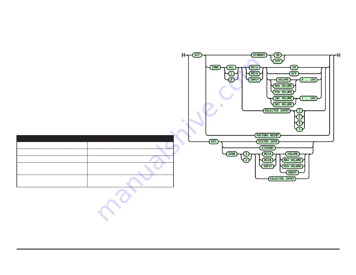
Figure 16.

 RS232 Text Command Diagram

RS232 Control

The RS232 control port allows controlling the PREZONE2 via an external device 

using text command protocol.
The protocol uses SET and GET as the first part of the command structure. SET  

may be used to change values in the device while GET may be used to gather 

information about the device.
GET and SET must be followed by details of the items to be controlled or queried. 

Basic rules and tips for successful RS232 communication are below. 
•  A valid command is always answered with OK CR LF
•  An invalid command is always answered with ERROR CR LF
•  All commands must end with CR, LF or CR LF depending on the controlling 

device and program being used.

•  Only ASCII characters are allowed (UTF-8 is not supported).
•  Keywords are 

not

 case-sensitive.

•  The commanding device must wait for a response (OK CR LF or ERROR 

CR LF) before sending a command that changes the same setting.

Test Command Examples

Text Command

Action/Response

set zone 2 selected input 3 CR

Selects a source in Zone 2

set zone 1 input volume 60 CR

Changes the audio level in Zone 1

set zone all mica inc volume 5 CR

Increments the MIC A level in both zones

get zone 2 micb onoff CR

Checks mute status of MIC B in Zone 2. 

Response will be: ON CR or OFF CR

get system info CR

Gets all settings of the PREZONE2. Response will 

be a list of all current device settings.

Notifications

External devices will be receive PREZONE2 state notifications via RS232. If 

a device parameter changes, a message will be sent out over RS232 to the 

external device.This can be a volume update or a signal / clip LED change. 

These notifications are normal ASCII text and are similar to the text commands 

except they do not contain the SET or GET keyword. All notifications will end 

with CR LF.
Using the notifications is highly recommended over polling the PREZONE2 from 

the external device via get messages.

Figure 16 gives possible text commands. By following the connections from the 

left to right, valid commands may be created.

Содержание PREZONE2

Страница 1: ...ric shock the external wiring connected to the terminals marked with class 2 wiring requires installation of class 2 wiring by an authorized trained person or by using ready made leads or cords This unit has NOT been designed for use in mobile applications such as mobile discobars mobile PA systems live bands and audio rental systems Using it in such applications will lead to product damage and sa...

Страница 2: ...utton controls for two distinct zones of audio outputs and an array of LEDs that give status of numerous functions of the device Rotary encoders volume controls feature LED indication of the actual volume level Adhesive labels may be applied to indicate zone sources and outputs 1 Standby Initiates or disables manual standby mode Indicates status of standby mode 2 Zone 1 Volume Control Rotary volum...

Страница 3: ... panel LED PAG the PAG indicator on the webapp and a RS232 notification Activating the paging mode will also activate the priority output of the selected zone s 3 MIC A Input MIC A input has the 3rd highest priority of all inputs The input connection accepts a balanced microphone or line level audio signal via the Euroblock connector and a stereo line level via RCA connectors A pushbutton allows s...

Страница 4: ...r cable 11 Auto Standby Enables Disables auto standby mode 12 Priority Out 3 pin Euroblock connector with two 24 VDC priority signals Active when either the Emergency Input or Paging is active to the zone connected Overides external volume controls present on speaker lines so emergency or paging messages are audible regardless of physical volume control status 13 RS232 3 Pin Euroblock connector th...

Страница 5: ...ts on the back panel Wiring Emergency Input 1 See Figure 2 Connect a balanced 0 dBV line level emergency input audio signal to the Euroblock connector 2 If available connect the emergency contact to the mute all connection The contact must be potential free a relay or switch contact that does not carry any voltage 3 Alternatively activate the VOX circuitry by turning the VOX control until there is...

Страница 6: ... activated the VOX circuit will attenuate all lower priority sources MIC B Input 1 4 by 30 dB in the zone s where MIC A is enabled 9 Volume may be set using the front panel level control MIC Input A or B may be activated by pressing the respective MIC A or B select switch on the front panel Wiring Inputs 1 4 1 See Figure 6 Connect source inputs as required Input 1 has Euroblock connectors that acc...

Страница 7: ...o an individual device with CAT5e or better cable 2 Once connected users have several options to access a fully responsive webapp to operate the PREZONE2 See Network Connections for more information on network configuration and accessing the webapp control page Wiring Priority Out 1 See Figure 9 Connect the 3 pin Euroblock to the override relay in any line in volume controls wired in the loudspeak...

Страница 8: ...ddress and configure In a routed network the PREZONE2 will obtain an IP address via DHCP In a switch network or direct connection to a controlling device the PREZONE2 will auto generate a link local address Factory default hostname is prezone2 which may be changed in the webapp connecting via hostname is the most reliable way to connect to the PREZONE2 Further information on PREZONE2 connections a...

Страница 9: ...IP address Figure 12 shows a direct connection from the PREZONE2 through the router and wireless connections of various devices PREZONE2 will auto configure and automatically obtain an IP address Figure 13 shows a direct connection from the PREZONE2 to a PC via Ethernet This connection does not require any manual IP settings link local both devices auto negotiate Figure 13 Direct Ethernet Connecti...

Страница 10: ...us of clipping paging and emergency mode status 2 MIC A and B Controls The MIC A and B rotary dials control the level of the respective microphone input of the zone selected The loudspeaker icon in the middle of the dial turns the microphone on or off 3 Line Level Control This rotary level control adjusts the volume of the selected source The loudspeaker icon in the middle of the dial turns the so...

Страница 11: ...ume Limits Allows adjusting minimum and maximum level controls for MIC A MIC B and Line music levels for each zone via a volume limit slider There must be a minimum 10 difference between the minimum and maximum volume levels 5 Password A password can be added to limit access to the settings page 6 Factory Reset This allows a full factory reset of the device All settings will be erased and returned...

Страница 12: ...mand that changes the same setting Test Command Examples Text Command Action Response set zone 2 selected input 3 CR Selects a source in Zone 2 set zone 1 input volume 60 CR Changes the audio level in Zone 1 set zone all mica inc volume 5 CR Increments the MIC A level in both zones get zone 2 micb onoff CR Checks mute status of MIC B in Zone 2 Response will be ON CR or OFF CR get system info CR Ge...

Страница 13: ... Guide PREZONE2 PREZONE2 Block Diagram Figure 17 below gives a signal flow block diagram of the PREZONE2 The key at the bottom right shows which blocks are located on the front and back panels respectively Figure 17 Signal Flow Diagram ...

Страница 14: ...ormation contained in this manual was complete and accurate at the time of printing However due to ongoing technical advances changes or modifications may have occurred that are not covered in this manual The latest version is available at www biamp com FEB 2020 CONTACT US Email support biamp com Web support biamp com ...

Отзывы: