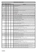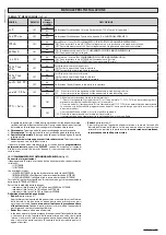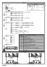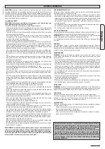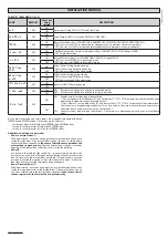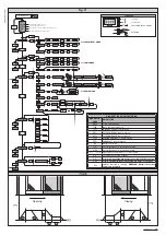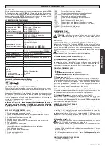
INSTALLATION MANUAL
During closing, it carries out a reopening manoeuvre.
- Internal radar:
Opens, with the door open, it triggers the automatic closing time; if activated
while the door is open, it sets automatic closing time to zero. If clear time was
active - activated by an Open-key operation - with the door open, this time is
converted into automatic closing time. Following the automatic closing time,
the door closes. During closing, it causes the door to open again.
- Opening photocell:
During opening, it stops movement until the photocell is cleared. With the
door open, it sets the TCA or clear time to zero. If triggered, it prevents the
door from starting to open and close.
- Closing photocell:
During closing, it reverses movement. With the door open, it sets the TCA or
clear time to zero. If triggered, it prevents the door from starting to open and
close.
- Stop:
Stops movement and cancels all commands.
Mode 1) Door closed by day
This differs from standard mode as follows:
- the door closes slowly and stays closed
- panic function active
- only Open-key input is active (opens quickly, stays open for clear time, closes
slowly)
- during closing, the photocells stop movement for as long as they remain
triggered, without reopening the door.
In cage mode, this type of operation is not permitted.
Mode 2) Door closed at night
This differs from standard mode as follows:
- panic function not active.
- only Open-key input is active (opens quickly, stays open for clear time, closes
slowly).
- during closing, the photocells stop movement for as long as they remain
triggered, without reopening the door.
In cage mode, the internal and external doors are set as “closed by night”.
Mode 3) Totally opened door
This differs from standard mode as follows:
- the door opens totally at slow speed and stays open
Mode 4) Partially opened door
This differs from standard mode as follows:
- the door opens partially (distance according to “partial opening” setting) at
slow speed and stays open.
In cage mode, this type of operation is not permitted.
Mode 5) Partial opening
This differs from standard mode as follows:
- like standard mode, except opening stops at the partial distance entered as
the “partial opening” setting.
In cage mode, the internal and external doors are set as “partial open”.
Mode 6) Chemist’s opening
This differs from standard mode as follows:
- the door opens and closes at slow speed and stops at the value entered for
“chemist’s opening”.
- only the Open-key command is enabled
- automatic closing is not enabled.
- during closing, the photocells stop movement for as long as they remain
triggered, without reopening the door.
In cage mode, this type of operation is not permitted.
Mode 7) cage open to inside (Enabled in cage mode only)
The external door is set as “closed by day”.
The internal door is set as “total open”.
Mode 8) cage open to outside (Enabled in cage mode only)
The external door is set as “total open”. The internal door is set as “closed by day”.
15.2) RADAR OPERATION MODE
Mode 0) Radar in standard mode:
- internal radar control enabled
- external radar control enabled
Mode 1) Internal radar:
- internal radar only enabled
(in cage mode, only the radar inside the building is enabled)
Mode 2) External radar:
- external radar only enabled
(in cage mode, only the radar outside the building is enabled)
15.3) BUZZER OPERATION MODE
Mode 0:
he buzzer does not sound during opening/closing. It is only triggered in an
emergency to report.
Mode 1:
The buzzer sounds at the beginning of each opening operation or when move
-
ment is reversed.
Mode 2:
The buzzer sounds at the beginning of each opening and closing operation or
when movement is reversed.
Mode 3:
The buzzer sounds for the full duration of operation.
15.4) LOCKING DEVICE OPERATION MODE
Mode 0:
Motor always free (lock always powered).
Mode 1:
Motor locked on closing position.
Mode 2:
Motor locked every time it is stopped.
Mode 3:
Motor locked every time it is stopped for more than 20 sec.
Mode 4:
Motor reacts with 10N to forced opening.
Mode 5:
Motor reacts with maximum force to forced opening.
15.5) EMERGENCY INPUT OPERATION MODE
Mode 0:
NO input, opens and stays open for as long as the input is active.
Mode 1:
NO input, closes and stays closed for as long as the input is active.
Mode 2:
NC input, opens and stays open for as long as the input is active.
Mode 3:
NC input, closes and stays closed for as long as the input is active.
15.6) ALARM OUTPUT OPERATION MODE
The alarm output is activated in the following cases:
- the door stays open as a result of the photocell being triggered for longer
than the time entered for the “alarm_time” parameter;
- there is an obstacle alarm;
- opening is being forced while the door is applying an opposite force (lock
mode = 4 or 5);
The alarm output is deactivated in the following cases:
- when the closing travel limit is reached
- when the stop key is pressed
15.7) DOOR STATUS OUTPUT OPERATION MODE
Mode 0:
Output active if the door is not fully closed
Mode 1:
Output active if the door is not fully open
15.8) ANTI-PANIC FUNCTION
“ON”
When there is no mains power and the battery is connected, the door per-
forms a complete opening cycle and then stops in the open position.
“OFF”
When there is no mains power, the door opens and stays open if battery
voltage drops below 20V.
15.9) ANTI-CRUSH FEATURE
If an obstacle interferes with the door’s movement, slowing it down, the door’s
movement is reversed during closing, or it is stopped during opening. Sensitivity
can be adjusted on the display.
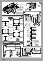
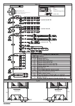
15.10) CONNECTING A NUMBER OF DOORS WITH CENTRAL CONTROL PANELS (Fig.
AH)
Serial line connections to produce a hardwired centralized control system must
be made using only 2-wire cabling of the kind used for telephone systems.
The length of the cable between one unit and the next must not be greater
than 250 m.
The master panel is the one that sends commands to all the other panels belonging
to the same zone. Only one master can be specified per zone. A zone comprises
one or more doors connected to each other. Different zones are identified se
-
parately with a different number, which can be set via the DISPLAY or using a
universal handheld programmer
.
Possible commands through a central controller are:
a) Open-key via button. All doors belonging to the same zone open and, once
the set clear time is up, close again, returning to the mode set with the master
unit’s mode selector. This command is useful for entering in the morning and
leaving once the closed by night function has been set.
b) Closed by night. All doors belonging to the zone enter closed-by-night
mode.
c) Closed by day. All doors belonging to the zone enter closed-by-day mode.
d) Total/partial opening. All doors belonging to the zone enter total/partial-open
mode.
e) Internal/external radar or with external radar only. All doors belonging to the
zone open with internal radar only.
The zone number is set on each card via the universal handheld programmer
or
DISPLAY. Zone 0 is earmarked for commands to the whole network, i.e. if a
master unit is set with zone 0, its commands are executed by all zones.
15.11) CONNECTING 2 DOORS IN cage MODE (Fig. AG)
Connections and settings:
cage mode comprises 2 automatic doors, connected via 485 serial line:
- (1) EXTERNAL
- (2) INTERNAL
3 radars are connected:
- (A) EXTERNAL RADAR (connected to the EXTERNAL card’s external radar)
- (B) CENTRAL RADAR (connected to the EXTERNAL card’s internal radar)
- (C) INTERNAL RADAR (connected to the INTERNAL card’s internal radar)
D811590 00100_01
22
- VISTA SL
Содержание VISTA SL
Страница 2: ...D811590 00100_01 2 VISTA SL ...

