INSTALLATION MANUAL
DL5
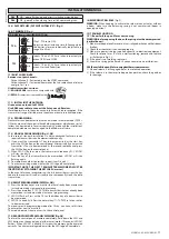
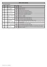
SWO - goes off when opening limit switch command given.
DL6
SWC - goes off when closing limit switch command given.
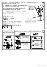
16.2) DIP SWITCHES (DIP SWITCH TABLE “A” ) (Fig. J)
16.3) TRIMMERS (Fig. J)
TRIMMER
ADJUSTMENTS
DESCRIPTION
TCA
0
sec.
(Dip1 - TCA set to ON).
Adjusts automatic closing time, following which
the barrier closes automatically (adjustable in
range 0 to 90 sec.).
90
sec.
TW
min.
Inputs 7-8 and 19-20 are taken respectively to
mean OPEN and CLOSE.
max.
Inputs 7-8 and 19-20 are taken respectively to
mean Start and Pedestrian.
17) BUILT-IN RECEIVER
Receiver’s output channels:
- Output channel 1, if activated, gives the START command.
- Output channel 2, if activated, commands the 2nd radio channel relay to
energize for 1 sec..
Usable transmitter versions:
All ROLLING CODE transmitters compatible with:
.
All REPLAY transmitters compatible with:
.
17.1) INSTALLING THE ANTENNA
Use an antenna tuned to 433MHz.
Use RG58 coax cable to connect the Antenna and Receiver.
Metal bodies close to the antenna can interfere with radio reception. If the
transmitter’s range is limited, move the antenna to a more suitable position.
17.2) PROGRAMMING
Transmitters can be memorized in manual mode, in remote mode (DIP 6 =
ON) or by means of the universal handheld programmer, which means instal-
lations can be created in “receiver community” mode and the installation’s
complete database can be managed via the EEdbase software.
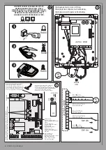
17.3) MANUAL PROGRAMMING (Fig. H, AE)
In the case of standard installations in which advanced features are not
required, transmitters can be memorized manually.
1) If you want the transmitter's T key to be memorized as the start key,
press the SW1 button on the control panel. Alternatively, if you want the
transmitter's T key to be memorized as the second radio channel, press
the SW2 button on the control panel
2) When LED DL1 flashes, press the transmitter's hidden key P1. LED DL1
will stay steadily lit.
3) Press the key of the transmitter to be memorized, LED DL1 will start
flashing again.
4) To memorize another transmitter, repeat steps 2) and 3).
5) To exit memorizing mode, wait for the LED to go off completely.
IMPORTANT NOTE: THE FIRST TRANSMITTER MEMORIZED MUST BE
IDENTIFIED BY ATTACHING THE KEY LABEL (master).
In the event of manual programming, the first transmitter assigns the key
code to the receiver: this code is required to subsequently clone the radio
transmitters.
17.4) REMOTE PROGRAMMING (DIP SW 6= ON).
1) Press the hidden key of a transmitter that has already been memorized
in standard mode via manual programming.
2) Press the normal key (T1-T2-T3-T4) of a transmitter that has already been
memorized in standard mode via manual programming.
3) LED DL1 flashes. Press within 10 sec. the hidden key of a transmitter to
be memorized.
4) LED DL1 is steadily lit. Press the normal key (T1-T2-T3-T4) of a transmitter
to be memorized.
The receiver exits programming mode after 10 sec.: you can use this time
to enter other new transmitters.
This mode does not require access to the control panel.
17.5) ERASING THE CONTROL PANEL’S MEMORY (Fig. AE)
To erase the control panel’s memory completely, hold down the SW1 and
SW2 buttons on the control panel at the same time for 10 seconds (LED DL1
flashes). When LED DL1 is steadily lit it means the memory has been erased
correctly. To exit memorizing mode, wait for the LED to go off completely.
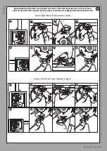
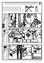
18) EMERGENCY RELEASE (Fig. Y)
WARNING: When needing to activate the release in an actuator without
a boom, make sure the balancing spring is not compressed (boom in
opening position).
19) TROUBLESHOOTING.
19.1) Boom fails to open. Motor not running.
WARNING: before opening the door, the spring must be decompressed
(vertical boom).
1) Make sure the photocells are not dirty, misaligned or have had their beam
broken.
2) Check that the motor is connected properly.
3) Make sure power is being supplied correctly to electronic equipment.
Check for blown fuses. If a fuse is malfunctioning, remove and replace
as illustrated in Fig. I, J.
4) If the panel is not working, replace it.
5) Grease the spring guide tie rods if you encounter noise or vibrations.
20.2) Boom fails to open. Motor running but there is no movement.
1) Manual release is still engaged. Reset to motorized operation.
2) If the release is in the motorized operation position, check the gearbox
for damage.
MOOVI 30-60 - ALPHA BOM
-
17
D811997 00100_02
Содержание Moovi 30 Alpha Bom
Страница 2: ...2 MOOVI 30 60 ALPHA BOM D811997 00100_02...

