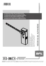
INSTALLATION MANUAL
2) GENERAL INFORMATION
Compact electromechanical barrier suitable for enclosing private areas and
car parks and for use across entrances used by vehicle traffic only. Available
for entrance/exit points between 3 and 5 metres across. Adjustable electro-
mechanical limit switches ensure the boom stops in the correct position.
The emergency release for manual operation is operated by a lock with a
personalized key.
The actuator is always supplied ready for assembly on the left.
Where necessary, the opening direction can always be reversed with a
few simple operations. The foundation base mod. CBO (on request) can
be supplied to make the barrier easier to install.
Provision for accessories makes installing them straightforward, with no
need to drill additional holes.
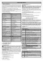
3) TECHNICAL SPECIFICATIONS
MOTOR
Power supply:
220-230 V 50/60 Hz(*)
Max. power input:
300W
Capacitor:
8µF 450V (220-230V): 32µF 250V (110V)
Current demand (with accessories): 1,4 A: 2.8 A
Insulation class:
F
Internal lubrication:
lifetime greased
Max. torque:
85 Nm (MOOVI 30)
250 Nm (MOOVI 60)
Opening time:
4s (MOOVI 30)
8s (MOOVI 60)
Boom length:
3m max (MOOVI 30)
6m max (MOOVI 60)
Impact reaction (Safety Edge):
stop or stop and reverse
Mechanical manual release:
personalized key
Type of boom:
rectangular
Limit switches:
electric, built-in and adjustable
Type of use
semi intensive
Operating temperature range:
da -10°C a +55°C
Protection rating:
IP 24
Actuator weight (without boom):
35,6 Kg
Flashing light:
220-230V~ 25W max
Dimensions:
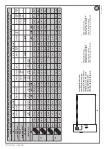
see fig.A
CONTROL UNIT
Accessories power supply:
24V~(demand max. 180mA)
Fuses:
see figures I, J
Max. motor output:
500 W
Work time:
max. 10 sec.
(*)= special supply voltages to order
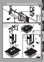
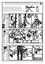
4.1) FOUNDATION PLATE (Fig.B1)
4.2) ANCHOR BOLTS (Fig.B2)
5) ACTUATOR ASSEMBLY
WARNING! The barrier must be used only for entrance/exit points
intended for vehicle traffic. Pedestrians must not be allowed to pass
within range of the automated system. Make sure there is a separate
entrance/exit just for pedestrians.
The entrance/exit must be suitably signposted with the compulsory
signs illustrated in Fig.A.
WARNING: before opening the door, the spring must be decompressed
(vertical boom). The door in the cabinet must face towards the inside of the
property. Standing in the middle of the entrance, facing out, if the cabinet
is on your left, the barrier is on your left: if the cabinet is on your right, the
barrier is on your right.
The actuator is always supplied ready for assembly on the left.
6) Assembly on left (Fig. A, B, C, D).
- Balance the boom as illustrated in Fig. AB.
7) Assembly on right (Fig. AA).
- Balance the boom as illustrated in Fig. AB.
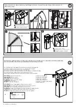
8) Boom assembly (Fig. D).
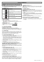
9) BOOM BALANCING (Fig. AB).
For Moovi 30:
WARNING! During the closing operation, the balancing spring
must never be fully compressed. Fig.AB rif.3 shows the position
for determining the minimum size that the compressed spring can be
allowed to reach with the boom in the open position (vertical).
10) MOOVI accessories (boom length limits and balancing) (Fig. AF)
For further information on installing and using the accessories, refer to the
relevant instruction manual.
11) FITTING THE FLASHING LIGHT (FIG.AC)
Complete assembly and wiring as directed in instructions provided for
the flashing light
12) FITTING THE PHOTOCELL (FIG. AD).
Complete assembly as directed in instructions provided for the photocell
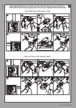
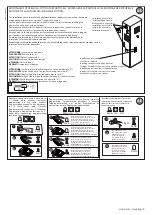
13) ADJUSTING THE LIMIT SWITCHES (Fig. G)
----------------------------------------------------------
14) PREPARING THE ELECTRICAL SYSTEM
WARNING: before opening the door, the spring must be decompressed
(vertical boom). Prepare the electrical system (fig. A), referring to the stan-
dards in force. Keep mains power connections well separated from service
connections (photocells, safety edges, control devices, etc.).
WARNING! For connection to the mains power supply, use a multicore
cable with a cross-section of at least 3x1.5mm
2
of the kind provided for
by the regulations mentioned above (by way of example, if the cable is
not protected, it must be rated H07 RN-F or higher, while if it is protected
it must be rated at least H05 VV-F with a cross-section of 3x1.5mm
2
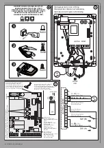
).
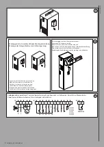
15) WIRING (FIG. F, I, J)
WARNING: Wiring must be carried out by qualified, expert personnel in a
professional manner and in accordance with all regulations in force, using
appropriate materials.
BORNE
DESCRIPTION
1-2
Power supply 220-230 V 50/60 Hz (Neutral to terminal 1).
3-4-5
Motor M connection (terminal 4 common, terminals 3-5
motor start and capacitor).
1-4
220-230V flashing light connection
7-8
START input or key selector (N.O.) with trimmer TW=max.
OPEN input (N.O.) with trimmer TW=min.
7-9
STOP button (N.C.). If not used, leave jumpered.
7-10
Photocell or pneumatic safety edge input (N.C.). If not used,
leave jumpered.
7-11
Opening limit switch (N.C.). If not used, leave jumpered.
7-12
Closing limit switch (N.C.). If not used, leave jumpered.
13-14
24 V~output to supply photocell and other devices.
15-16
Output for barrier open light / 2nd radio channel.
17-18
Antenna receiver input (17 signal 18 braiding).
19-20
PEDESTRIAN input (N.O.) with trimmer TW=max.
CLOSE input (N.O.) with trimmer TW=min.
JP4
1-2 channel radio-receiver board connector.
16) ADJUSTMENTS
RECOMMENDED ADJUSTMENT SEQUENCE:
Adjusting the limit switches (Fig. G)
Programming transmitters (Fig. H)
Setting of parameters/logic, where necessary
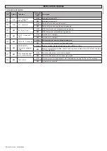
16.1) LEDs (Fig. J)
ALPHA-ALPHA BOM control panels feature a series of self-diagnosis LEDs via
which all functions can be monitored. LED functions are as follows:
LED
DESCRIPTION
DL1
Built-in radio receiver LED.
DL2
START (trimmer TW=max) - lights when START command given
OPEN (trimmer TW=min) - lights when OPEN command given
DL3
STOP - goes off when Stop command given.
DL4
PHOT - goes off when photocells are not aligned or when there
is an obstacle.
16
-
MOOVI 30-60 - ALPHA BOM
D811997 00100_02
Содержание Moovi 30 Alpha Bom
Страница 2: ...2 MOOVI 30 60 ALPHA BOM D811997 00100_02...

