10
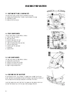
11. INSTRUMENT PANEL COMPONENTS
The instrument panel components are identified as follows:
A. Paddles to activate brushes / traction (located beneath the grip)
B. ON/OFF key switch
C. Battery level / hour meter
12. REAR COMPONENTS
The rear components are identified as follows:
A. Pedal to raise the brushes
B. Water level tube
C. Solution tank water inlet cap
D. Drain hose of recovery tank
E. Latch to lock down the recovery tank
F. Storage compartment
H. Lever to raise the squeegee
I. Brake lever
J. Solution filter
13. SIDE COMPONENTS
The side components are identified as follows:
A. Solution flow control valve
B. Handle to raise the recovery tank
C. Handle to raise the vacuum unit
D. Upper storage compartment
14. ASSEMBLING THE SQUEEGEE
For packaging reasons, the squeegee is supplied disassembled from the ma-
chine, and must be assembled as shown in the figure, inserting the small pin of
the squeegee into the coupling mechanism until it locks into place.
Install the squeegee vacuum hose over the squeegee shoe adapter and be cer-
tain that the vacuum hose in to the right of the squeegee lift cable.
MACHINE PREPARATION
Содержание E29941-00
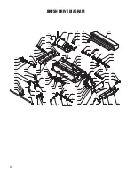
Страница 20: ...20 BRUSH DECK DIAGRAM 1 12 21 5 10 7 18 15 2 19 9 11 18 7 10 4 3 8 20 13 14 16 6 17 12 5 23 24 22 24 ...
Страница 36: ...36 SOLUTION CONTROL DIAGRAM 11 23 9 19 21 13 20 6 5 15 16 4 1 22 10 3 14 8 1 8 2 17 12 18 2 ...
Страница 40: ...40 ELECTRICAL COMPONENTS DIAGRAM 3 1 18 21 5 14 15 11 7 8 12 16 2 11 8 24 9 17 6 13 20 4 22 19 10 ...
Страница 42: ...42 ELECTRICAL DIAGRAM ...
Страница 51: ...51 ...


