background image

Service and Maintenance

7KC Series Service Manual

3–5

Replacing the

inside rose

To remove the inside rose:

1. Remove the inside lever (

page 3–2

).

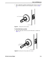
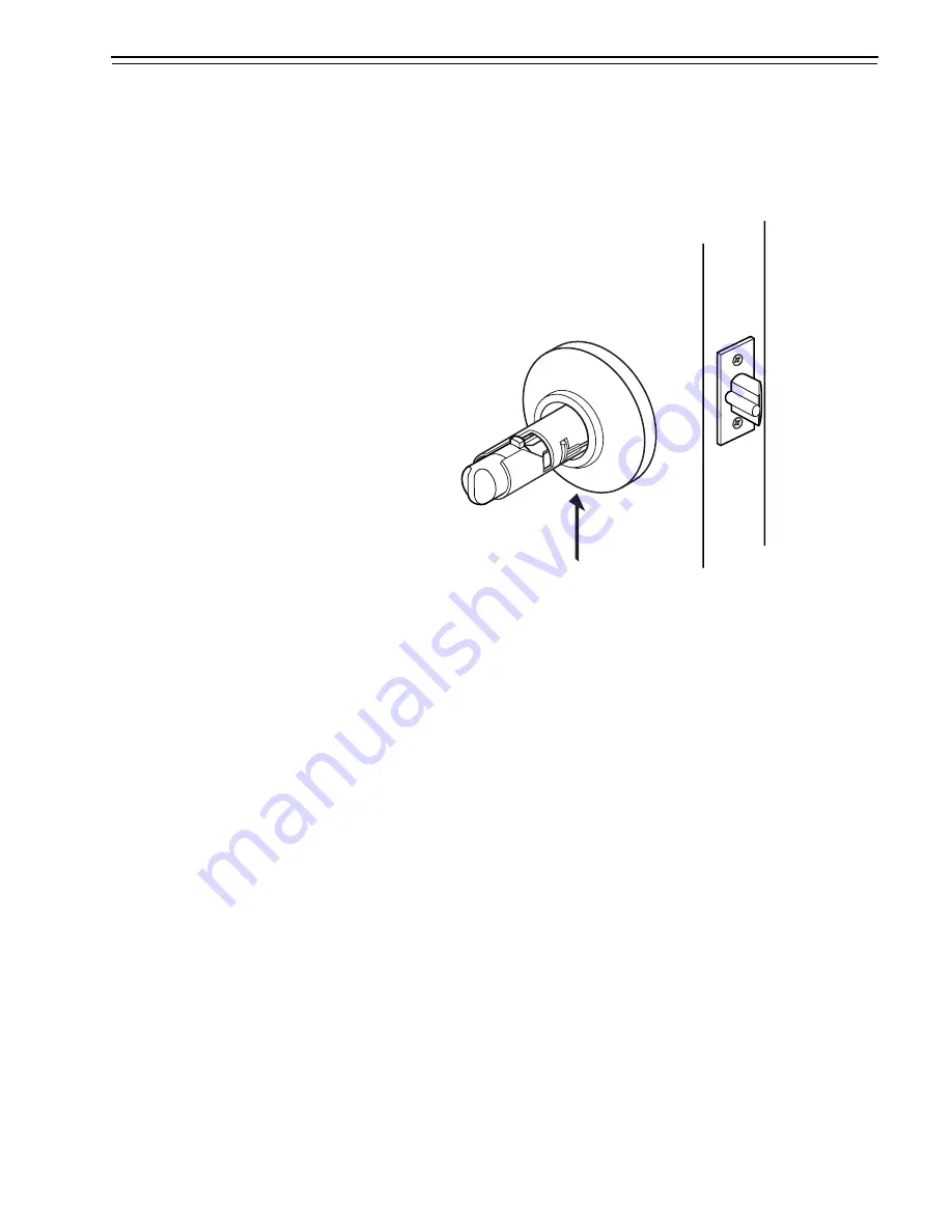
2. Insert a flat blade screwdriver in the slot between the rose and liner, 

as shown in 

Figure 3.4

. Pry the rose until it pops off the liner.

3. Unscrew the two through-bolts. Save the through-bolts.

4. Slide the liner off the sleeve. Save the liner.

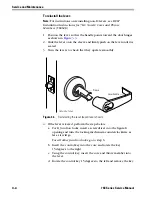
To reinstall the inside rose:

1. Align the holes in the liner with the holes prepared in the door, as 

shown in 

Figure 3.5

.

2. Install the two through-bolts through the liner and door in the top 

and bottom holes.

3. Tighten the liner onto the door with the through-bolts.

4. Align the slot in the rose with the tab on the liner and firmly press 

until the rose is flush with the door.

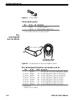
Figure 3.4

Removing the inside rose with the screwdriver

Inside of door

Location of the slot in the rose

Содержание 72KC

Страница 1: ......

Страница 2: ...s No part of this manual and or databases may be reproduced or transmitted in any form or by any means electronic or mechanical including photocopying recording or information storage and retrieval sy...

Страница 3: ...chnical support 1 3 FUNCTIONS AND PARTS LISTS 2 1 Function descriptions 2 2 Single keyed functions 2 2 Non keyed functions 2 3 Functions by ANSI designation 2 3 AB function chassis and trim entrance l...

Страница 4: ...assembly 3 8 Lubricating the cores 3 10 Aligning the chassis and trim 3 11 Troubleshooting 3 12 INSTALLATION INSTRUCTIONS A 1 Position template 1 3 Bore two holes and install latch 1 3 Install boring...

Страница 5: ...ever 3 2 Removing the plain lever or button lever 3 3 Reinstalling the lever keyed lever shown 3 4 Removing the inside rose with the screwdriver 3 5 Reinstalling the inside rose and rose liner 3 6 Rem...

Страница 6: ...Figures vi 7KC Series Service Manual...

Страница 7: ...FICATIONS AND STANDARDS The product complies with ANSI A156 2 Series 4000 Grade 2 standards California Administrative Code Title 19 and Title 24 Illinois Accessibility Standard The locks are listed by...

Страница 8: ...K08 Template for Door and Frame Preparation for 63K 73KC 83K 93K Cylindrical Locks with Small STK Strike T56052 K09 Template for Door and Frame Preparation for 63K 73KC 83K 93K Cylindrical Locks with...

Страница 9: ...n your area whenever you need help Before you call however please make sure you are where the 7KC Series Lock is and that you are prepared to give the following information what happened and what you...

Страница 10: ...Getting Started 1 4 7KC Series Service Manual...

Страница 11: ...l 2 1 2 FUNCTIONS AND PARTS LISTS The following pages contain function descriptions for all 7KC Series Locks This chapter also includes an exploded diagram of a lock as well as diagrams of trim and ot...

Страница 12: ...ding function drawings Outside Inside Latch Shading indicates that the lever is fixed View looking down at the top of the door AB Entrance ANSI F109 D Storeroom ANSI F86 Latchbolt operated by inside l...

Страница 13: ...75 Latchbolt operated by inside lever outside lever when not locked Outside lever locked by inside button Outside lever unlocked by inside lever outside slotted button when rotated counterclockwise cl...

Страница 14: ...NSI F109 This diagram shows the AB function lock The chassis without trim and individual chassis parts are not available to order See the following pages for part numbers For levers see page 2 7 For r...

Страница 15: ...3 Strikes and strike boxes 1 2 4 3 5 Item Nomen clature Part no Specify finish Qty Description 1 8KS1 B25640 1 Standard steel strike box 2 6KS2 Includes one A53761 strike two A25359 strike screws and...

Страница 16: ...833712 1 Inside rose liner 2 A55557 2 Through bolt screw 3 B56164 1 Outside rose not shown 1833754 1 Outside rose liner Figure 2 5 Buttons 1 2 3 Finish Item 1 Turn button assembly Item 2 Slotted butto...

Страница 17: ...Lever style 15 Lever style 16 1 2 3 6 5 4 7 8 9 Style Item Part no Specify finish Description 1 D56159 Plain lever handle 14 2 D56157 Button lever handle 3 D56158 Keyed lever handle 4 D56155 Plain lev...

Страница 18: ...ylinders View looking inside the end of the lever shaft End of the lever shaft 1 Item Part no Finish Description 1 D56156 Specify finish 15 Keyed lever for non interchangeable cylinders not shown 1888...

Страница 19: ...adlocking latch with wide face 1 1 8 2 A25359 N A N A Latch screw 3 B80189 6KL3 NF 2 3 4 Deadlocking latch with narrow face 1 not shown B80113 6KL3 WF 2 3 4 Deadlocking latch with wide face 1 1 8 4 B8...

Страница 20: ...clature Part no Description 1 KD303 C55034 Drill jig 2 KD325 A01514 Strike plate locating pin 3 KD315 1350393 Faceplate marking chisel 1 1 8 2 1 4 not shown KD312 1487975 Faceplate marking chisel 1 2...

Страница 21: ...ig 2 KD325 A01514 Strike plate locating pin 3 KD315 1350393 Faceplate marking chisel 1 1 8 2 1 4 not shown KD312 1487975 Faceplate marking chisel 1 2 1 4 4 KD309 A54084 2 1 8 diameter chassis hole bit...

Страница 22: ...Functions and Parts Lists 2 12 7KC Series Service Manual...

Страница 23: ...ns instructions for replacing components servicing and maintaining components and troubleshooting common problems To See page Replace levers 3 2 Replace roses 3 5 Replace button assemblies 3 8 Lubrica...

Страница 24: ...rotate the key 15 degrees to the right 2 Remove the core and throw member from the lever 3 Insert a flat blade screwdriver into the figure 8 core hole and into the lever keeper 4 Press the screwdriver...

Страница 25: ...To remove the plain lever or button lever 1 Insert the knob keeper tool into the hole on the shaft of the lever as shown in Figure 3 2 2 Slide the lever off the sleeve Figure 3 2 Removing the plain l...

Страница 26: ...urn the levers to check that they operate smoothly 4 If the lever is keyed perform the steps below a For R function locks insert a screwdriver into the figure 8 opening and turn the locking mechanism...

Страница 27: ...lts 4 Slide the liner off the sleeve Save the liner To reinstall the inside rose 1 Align the holes in the liner with the holes prepared in the door as shown in Figure 3 5 2 Install the two through bol...

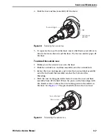
Страница 28: ...the following components levers page 3 2 inside rose and rose liner page 3 5 2 Slide the chassis assembly out of the door 3 Retract the rose locking pin and rotate the rose and liner assembly until it...

Страница 29: ...onto the outside hub 3 Retract the rose locking pin and rotate the rose and liner assembly onto the hub until the assembly reaches the bottom of the threading 4 With the rose locking pin still retrac...

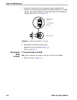
Страница 30: ...s frame and the latch tailpiece engages the retractor See Figure 3 8 6 Reinstall the following components inside rose and rose liner page 3 5 levers page 3 4 Replacing the button assembly To remove th...

Страница 31: ...ly from the locking bar as shown in Figure 3 9 To reinstall the button assembly 1 Align the button tab with the top slot in the sleeve as shown in Figure 3 10 Figure 3 9 Removing the button assembly I...

Страница 32: ...graphite into the keyhole Insert the key into the keyhole and remove it repeat several times 2 Allow the graphite to sift into the pin segment holes For silicone type lubrication 1 Clean all existing...

Страница 33: ...is frame and the latch tailpiece engages the retractor as shown in Figure 3 11 The outside rose and liner should also be flush with the door 3 If the chassis is not aligned with the latch or the outsi...

Страница 34: ...forth Figure 3 12 Adjusting the outside rose and liner assembly Outside rose and liner Rose locking pin Hub You notice Possible causes include You should Lever won t return to its normal position The...

Страница 35: ...7KC Series Service Manual A 1 A INSTALLATION INSTRUCTIONS The following pages contain the Installation Instructions for 72KC 75KC Cylindrical Locks...

Страница 36: ...Installation Instructions A 2 7KC Series Service Manual...

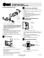
Страница 37: ...nter of the door 2 Drill a 1 diameter hole from the edge of the door that intersects the 2 1 8 hole 3 Mortise the door edge for the latch face 4 Install the latch through the 1 diameter hole For drive...

Страница 38: ...plate Caution The deadlocking plunger of the latchbolt must not enter the strike plate opening The plunger deadlocks the latchbolt and prevents forcing the latch when the door is closed A gap of more...

Страница 39: ...0 E exploded diagrams see part numbers and drawings F faceplate marking chisel 2 10 to 2 11 function description for AB function lock 2 2 for D function lock 2 2 for L function lock 2 3 for N function...

Страница 40: ...outside rose 3 7 removing button 3 8 inside rose 3 5 keyed lever 3 2 lock chassis from the door 3 6 outside rose 3 6 plain lever or button lever 3 3 roses part numbers and drawings for 2 6 reinstalli...

Отзывы: