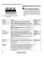
Installation Instructions for 45HM IDH Max® Mortise Locks
BEST ACCESS SYSTEMS
a Division of Stanley Security Solutions, Inc.
20
Troubleshooting the installation
4 With the door armed, attempt to exit through the
door.
The request-to-exit (RQE) feature should let you exit
without triggering an alarm by the access control panel.
5 Remove power from the lock and check whether the
door remains locked or is unlocked.
Verify that the lock fails safe or secure, according to its
function.
6 With the door armed, hold the door open. Hold a
magnet against the edge of the door, over the door
status sensor, until the access control panel sees the
door as closed. Then remove the magnet.
Verify that the appropriate alarm response is triggered
by the access control panel, indicating that the door
status sensor is working.
7 With the door armed, hold the door open. Hold a
magnet against the edge of the door, over the door
status sensor, until the access control panel sees the
door as closed. With the magnet in place, push in the
latchbolt.
Verify that the appropriate alarm response is triggered
by the access control panel, indicating that the
latchbolt status sensor is working.
Troubleshooting
To troubleshoot installation problems, refer to the table
below. For more information, refer to the
IDH Max Lock
Service Manual
(T60775) and to the documentation
provided by the manufacturer of the access control panel/
reader interface.
You notice . . .
Possible causes include . . .
You should . . .
Control electronics’ green status
LED and panel interface module’s
green status LED are steadily on.
Note:
You can check the control
electronic’s green status LED by
removing the access door from the
inside trim. You can see the
reflection of the LED inside the
upper-left corner of the trim.
Communication between the lock’s
control electronics circuit board and the
panel interface circuit board has been
interrupted.
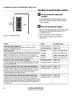
Make sure DIP switches 6 and 7 on the lock’s
control electronics circuit board are both set to ON
(automatic baud rate detection) or to the same
positions as DIP switches 2 and 3 on the panel
interface circuit board.
Check the connections for all communication field
wiring.
Check the communication connections between
the field wire harness and the wire transfer hinge.
Control electronics’ green status
LED is off.
Power is not being supplied to the lock.
Make sure that the lock’s power supply is
connected to electrical service.
Check the connections for all power field wiring to
the lock.
Check the power connections between the field
wire harness and the wire transfer hinge.
Panel interface module’s green
status LED is off.
Power is not being supplied to the panel
interface module.
Check the connections for power wiring between
the panel interface module and the access control
panel (or other power source).
A ‘door forced’ alarm occurs when
someone exits through the door.
RQE wiring, and door status and/or
latchbolt status wiring, is reversed
between the panel interface module and
the access control panel/reader interface.
Refer to
Connect panel interface module to access
control panel/reader interface
, on page 16, and
correct the wiring problem.
© 2006 Stanley Security Solutions, Inc. and Stanley Logistics, Inc.
T81624/Rev – 1921963 ER-7991-12 Dec 2006

