Installation Instructions for 45HM IDH Max® Mortise Locks
BEST ACCESS SYSTEMS
a Division of Stanley Security Solutions, Inc.
19
Installation Instructions for 45HM IDH Max® Mortise Locks
Testing the installation
27
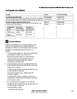
Test installation
Perform the following steps to test the installation. Also,
perform any standard testing recommended by the
manufacturer of the access control panel. If you encounter
problems, see
Troubleshooting the installation,
on
page 20.
1 Check the control electronics’ green status LED and the
panel interface module’s green status LED.
Both LEDs should be blinking, indicating that the
communication connection between the panel
interface circuit board and the lock’s control
electronics circuit board is OK.
2 After performing any necessary programming for the
lock and putting the door in a locked mode, use a valid
token to access the lock.
Confirm that the red reader LED, green reader LED, and
sounder respond as expected.
The lock should allow access, verifying that the
solenoid is working.
To check that the reader is working, view the lock’s
event history and verify that the information recorded
for the token is correct.
3 Use an invalid token to attempt to access the lock.
Confirm that the red reader LED, green reader LED, and
sounder respond as expected.
The lock should deny access.
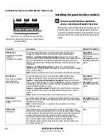
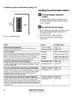
Sounder input configuration
Provides the ability to invert the interpretation of the sounder input signal.
The normal input configuration interprets a closed contact as sounder ON.
Normal input
Switch 7–ON
Inverted input
Switch 7–OFF
Function of TPR terminals and DLS terminals
Provides the ability to determine the function of the TPR terminals and
DLS terminals, as shown below.
Option 1
Switch 8–ON
Option 2
Switch 8–OFF
Feature
Option
DIP Switch Setting
Configuration
option
Function of
TPR terminals
Function of
DLS terminals
Option 1
(Switch 8–ON)
Communications
tamper
Door status &
latch status
Option 2
(Switch 8–OFF)
Latch status
Door status
– Continued on the next page


