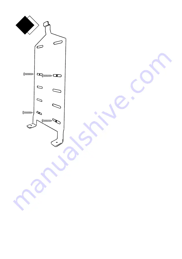
Step 2 - Positioning the Mounting Plate
The classic system should be positioned at the back bar where it can be easily seen by customers and staff. The lower
edge of the Mounting Plate should be 1420 to 1625mm (56" to 64") from floor level. You will need a clear space of at
least 380mm (15") between the base of the Wall Mounting Plate and the work surface or bar top. Make sure the power
lead will reach the power supply.
IMPORTANT: check the wall for hidden pipes or wires
1.
With a pencil, mark the wall where you wish the base of the system to be.
2.
Place the Mounting Plate in position and, through the slots, mark with the pencil where you wish to drill the four holes
for the screws. For the best fixing, keep the holes to the centre of the slots and avoid drilling between bricks.
3.
Put the Mounting Plate aside and select the correct drill-bit for the wall type.
4.
Drill four holes, each to a depth of 35mm and, protecting your eyes, blow clear any loose dust.
5.
For solid and dry lined walls, push in the Wall Plugs (narrow end first) and make sure that they are flush to the wall.
6.
Place the Mounting Plate in position and insert the four screws into the holes. Tighten lightly and then level the Mounting
Plate. Tighten the screws.
The Wall Mounting Plate is now secure.
2
Шаг 2 - Размещение монтажной пластины
Классическая система должна быть размещена на задней панели, чтобы ее
могли легко увидеть клиенты и персонал.
Нижний край монтажной пластины должен находиться на расстоянии
1420-1625 мм (56-64 дюйма) от уровня пола.
Вам потребуется свободное пространство не менее 380 мм (15 дюймов)
между основанием настенной монтажной панели и рабочей поверхностью
или верхней панелью.
Убедитесь, что провод питания дойдет до источника питания.
ВАЖНО: проверьте стену на наличие скрытых труб или проводов
1. С помощью карандаша отметьте стену там, где вы хотите, чтобы
основание системы было.
2. Установите монтажную пластину на место и отметьте карандашом там,
где вы хотите просверлить четыре отверстия для винтов. Для лучшей
фиксации держите отверстия в центре пазов и избегайте сверления между
кирпичами.
3. Отложите монтажную пластину в сторону и выберите правильное сверло
для типа стены.
4. Просверлите четыре отверстия, каждое на глубину 35 мм, и, защищая
глаза, удалите пыль.
5. Для сплошных и сухих облицованных стен вставьте дюбели (сначала
узким концом) и убедитесь, что они находятся на одном уровне со стеной.
6. Установите монтажную пластину на место и вставьте четыре винта в
отверстия. Слегка затяните, а затем выровняйте монтажную пластину.
Затянуть винты.
Настенная монтажная панель теперь
закреплена
.


