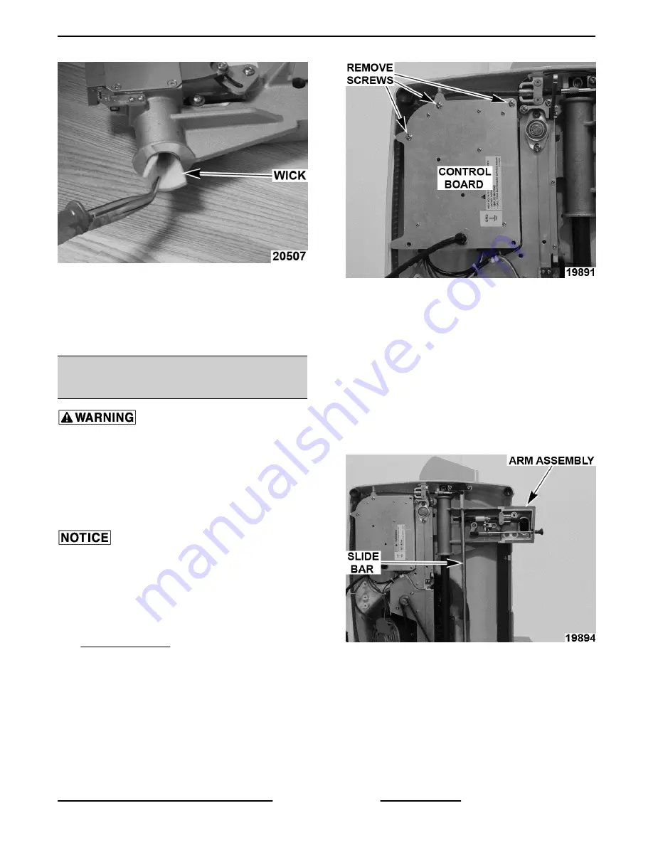
Berkel X13 Скачать руководство пользователя страница 29

Fig. 79

4.

Coat new wick with Berkel oil and install in
transport arm.

5.

Reverse procedure to install.

6.

Check slicer for proper operation.

SLIDE BAR SWITCH TEST (X13,

X13A)

Certain procedures in this section require
electrical test or measurements while power is
applied to the machine. Exercise extreme caution
at all times. If test points are not easily accessible,
disconnect power and follow lockout / tagout
procedures, attach test equipment and reapply
power to the test.

Certain components in this system are subject to
damage by electrostatic discharge (ESD) during field
repairs. An ESD kit is required to prevent damage. The
ESD kit must be used anytime the circuit board is
handled.

1.

Remove product table as outlined under
PRODUCT TABLE.

2.

Place slicer on its side, so it is resting on motor
housing.

3.

Remove screws to access control board.

Fig. 80

4.

Plug slicer in.

5.

Verify 5VDC between J4-1 and J4-5.

A.

If voltage is not present, check all
connections.

B.

If connections are good, replace control
board.

6.

Verify 5VDC between J4-4 and J4-5.

7.

Supporting the arm assembly, squeeze the slide
bar to the unlocked position and lower assembly.

Fig. 81

A.

Verify 0VDC between J4-4 and J4-5
anytime slide bar is squeezed into the
unlocked position.

B.

Verify 5VDC when slide bar is released
again.

8.

If voltage is not present, replace slide bar switch.

X13 SLICER - SERVICE PROCEDURES AND ADJUSTMENTS

Page 29 of 36

F25332 Rev. A (0718)

Содержание X13

Страница 1: ...ts and skills required to perform the procedure Procedures for which you do not have the necessary tools instruments and skills should be performed by a trained Berkel Service Technician The reproduct...

Страница 2: ...FE 13 KNIFE REMOVAL 13 RING GUARD 14 RING GUARD REMOVAL 14 INDEX KNOB 14 BOTTOM COVER X13A X13AE 15 15 AUTODRIVE MECHANISM X13A X13AE 15 AUTODRIVE MECHANISM REMOVAL 15 AUTODRIVE MECHANISM DISASSEMBLY...

Страница 3: ...X13AE 28 ECCENTRIC PIN ADJUSTMENT 28 WICK REPLACEMENT 28 SLIDE BAR SWITCH TEST X13 X13A 29 CARRIAGE SENSOR TEST X13 X13A 30 KNIFE MOTOR OHM TEST 30 CIRCUIT BREAKER TEST 31 ELECTRICAL OPERATION 32 COMP...

Страница 4: ...SERVICE UPDATES UPDATES July 2018 Added INDEX KNOB X13 SLICER SERVICE UPDATES F25332 Rev A 0718 Page 4 of 36...

Страница 5: ...Motor 1 2 H P Thickness Adjustable to slice a thickness up to 1 5 16 Slicing Speed Automatic Low 20 slices per minute Medium 40 slices per minute High 60 slices per minute Stroke Length Automatic Low...

Страница 6: ...to Clip Assembly South out Timer Assembly North out Sharpener North out Index Mechanism South out Use another magnet on the slicer to verify polarity of a replacement magnet Opposites attract X13 SLIC...

Страница 7: ...14 NOTE Parts 15 17 11 and 21 are left hand threaded on some older sharpeners B Remove deburring stone 13 and skirt 12 C Remove e clip 10 slide out shaft 5 while holding spring 16 D Remove spring 16 a...

Страница 8: ...ig 3 3 Slide product table off arm 4 Reverse procedure to install NOTE Make sure that dowel pin enters and rotates actuator arm interlock pacman Fig 4 5 Check slicer for proper operation PRODUCT TABLE...

Страница 9: ...backout if Loctite and primer is not used 7 Check slicer for proper operation ARM ASSEMBLY Arm Assembly Removal Disconnect the electrical power to the machine and follow lockout tagout procedures NOT...

Страница 10: ...isconnect X13A X13AE Fig 10 9 Remove screws and square rail NOTE Reposition arm assembly and remove bottom screw first Fig 11 10 Remove 2 screws securing round rail Fig 12 11 Remove round rail and arm...

Страница 11: ...quired to access part s being replaced 1 Remove screws and arm sensor Fig 15 2 Remove autodrive clutch plate screws Fig 16 3 Remove autodrive clutch plate and clip assembly 4 Remove screw autodrive cl...

Страница 12: ...ER PLATE Center Plate Removal Disconnect the electrical power to the machine and follow lockout tagout procedures 1 Close gauge plate 2 Move product table to home position 3 Turn center plate knob CCW...

Страница 13: ...lectrical and grounding connections must comply with the applicable portions of the National Electrical Code and or other local electrical codes NOTE Replace knife if it is less than 12 3 4 diameter 1...

Страница 14: ...e motor as outlined under KNIFE MOTOR AND MOUNT ASSEMBLY NOTE Knife motor just needs to be moved out of the way to access bolts and washers 4 Remove bottom two mounting bolts and washers Fig 28 5 Remo...

Страница 15: ...follow lockout tagout procedures Electrical and grounding connections must comply with the applicable portions of the National Electrical Code and or other local electrical codes 1 Place slicer on it...

Страница 16: ...todrive assembly Autodrive Mechanism Disassembly NOTE Remove only those parts required to access part s being replaced 1 Remove screws securing autodrive motor Fig 36 2 Remove autodrive motor and seco...

Страница 17: ...verse removal procedure to install 2 Place primary autodrive belt in clip assembly Fig 39 A Reconnect flex cable last and make sure cable is in front of guide assembly Fig 40 3 Check slicer for proper...

Страница 18: ...E Make sure tab on motor mount enters slot in slicer base Fig 43 3 Install drive belt as outlined under DRIVE BELT 4 Connect motor lead wires to control board 5 Check slicer for proper operation DRIVE...

Страница 19: ...outlined under AUTODRIVE MECHANISM X13A X13AE 3 Remove knife motor as outlined under KNIFE MOTOR AND MOUNT ASSEMBLY 4 Remove screws securing knife hub assembly to slicer wall Fig 45 5 Supporting hub t...

Страница 20: ...GAUGE PLATE ASSEMBLY Gauge Plate Assembly Removal Disconnect the electrical power to the machine and follow lockout tagout procedures 1 Open gauge plate and tape knife Fig 49 2 Remove gauge plate bolt...

Страница 21: ...to disconnect clevis from slide bar Fig 53 8 Remove screws and clamp Fig 54 A Remove cable from zipties 9 Unplug wire harness from control board 10 Remove knife motor as outlined under KNIFE MOTOR AN...

Страница 22: ...que mounting screws holding upper housing to slicer base 60 in lbs NOTE Two long screws go in bottom two holes 3 Check gauge plate for proper adjustment as outlined under GAUGE PLATE ADJUSTMENT 4 Chec...

Страница 23: ...e slicer on its side so it is resting on motor housing 2 Angle to knife A Loosen mounting screw Fig 56 B Turn adjustment screw until product table is at a right angle with gauge plate NOTE Adjustment...

Страница 24: ...Disconnect the electrical power to the machine and follow lockout tagout procedures NOTE With product table installed slide bar should be centered in carriage hole Fig 61 1 Remove clevis pin then slid...

Страница 25: ...o retract cable from index knob until index knob turns freely C Open index knob 1 4 turn and push cable in as far as it will go D Turn clevis until hole aligns with hole in interlock slide rod E Turn...

Страница 26: ...ll rubber boot away from adjustment block D Loosen top and bottom set screws NOTE Bottom set screw is underneath adjustment block opposite top set screw Fig 70 E Loosen center bolt and adjust gauge pl...

Страница 27: ...te all the way 3 Push product tray toward knife until built in stop in sharpener is actuated and hold for 5 seconds 4 Bring product tray back to home position 5 Check slicer for proper operation 6 Rep...

Страница 28: ...primary belt in auto clip assembly Fig 76 2 Remove screws and square rail Fig 77 3 Loosen nut and adjust eccentric pin accordingly 1 4 turn at a time Fig 78 4 Tighten nut 5 Recheck proper operation of...

Страница 29: ...revent damage The ESD kit must be used anytime the circuit board is handled 1 Remove product table as outlined under PRODUCT TABLE 2 Place slicer on its side so it is resting on motor housing 3 Remove...

Страница 30: ...age rod out 7 Verify 5VDC between J4 3 and J4 5 when arm assembly is in home position A 0VDC should be present anytime arm assembly is away from home position 8 If voltages are not all present replace...

Страница 31: ...pply power to the test 1 Place slicer on its side so it is resting on motor housing 2 Remove screws to access control board Fig 84 3 Plug slicer in 4 Verify 120VAC between J1 1 power cord neutral and...

Страница 32: ...OP button No of Flashes Problem Probable Cause 1 High temperature detected on control board Replace control board 2 Over current detected in control board DC motor shorted or control board malfunction...

Страница 33: ...switch closed 2 15VDC is applied to control board 3 Knife motor energized 4 Knife motor continues to run until stop button is pressed NOTE Slicers equipped with timer assembly will shut off after 15 s...

Страница 34: ...lit 3 Carriage tray secured A X13A only Slide bar switch closed control board signaled that carriage is in place Manual Sequence 1 Press start button start switch closed 2 15VDC is applied to control...

Страница 35: ...length LED will indicate selection 4 Press start button start switch closed 5 15VDC is applied to control board 6 Knife motor energized A Knife motor continues to run until stop button is pressed NOT...

Страница 36: ...malfunction 4 Belt mis aligned Noisy in automatic mode 1 Belts not properly tensioned 2 Belts worn 3 Auto motor malfunction Knife motor running knife not turning 1 Knife belt malfunction 2 Knife hub...

Отзывы: